76
Fig. 233
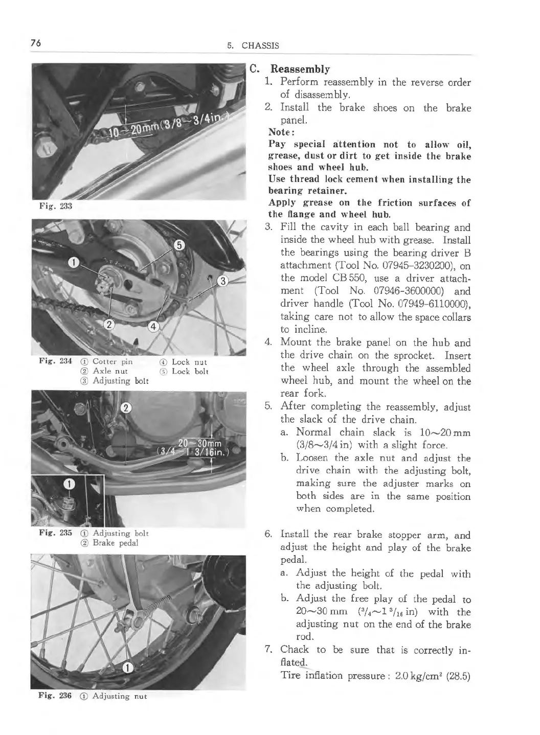
Fig. 234 <D Cotter pin © Lock nut
@ Axle nut ® Lock bolt
@ Adjusting bolt
Fig. 2.% <D Adjusting bolt
@ Brake pedal
Fig. 236 <D Adjusting nut
5. CHASSIS
C. Reassembly
1. Perform reassembly in the reverse order
of disassembly.
2. Install the brake shoes on the brake
panel.
Note:
Pay special atten tion not to allow oil,
grease, dust or dirt to get inside the brake
shoes and wheel hub.
Use thread lock cement when installing the
bearing retainer.
Apply grease on the friction surfa ces of
the flange and wheel hub.
3. Fill the cavity in each ball bearing and
inside the wheel hub with grease. Install
the bearings using the bearing driver B
attachment (Tool No. 07945-3230200), on
the model CB 550, use a driver attach-
ment (Tool No. 07946-3600000) and
driver handle (Tool No. 07949-6110000),
taking care not to allow the space collars
to incline.
4. Mount the brake panel on the hub and
the drive chain on the sprocket. Insert
the wheel axle through the assembled
wheel hub, and mount the wheel on the
rear fork.
5. After completing the reassembly, adjust
the slack of the drive chain.
a. Normal chain slack is
10~20 mm
(3/8~3 /4 in) with a slight force.
b. Loosen the axle nut and adjust the
drive chain with the adjusting bolt,
making sure the adjuster marks on
both sides are in the same position
when completed.
6. Install the rear brake stopper arm, and
adjust the height and play of the brake
pedal.
a. Adjust the height of the pedal with
the adjusting bolt.
b. Adjust the free play of the pedal to
20~30 mm (
3
/
4
~1
3
/
16
in) with the
adjusting nut on the end of the brake
rod.
7. Chack to
be sure that is correctly in-
flated.
Tire inflation pressure : 2.0 kg/cm
2
(28.5)
 Loading...