3 EN
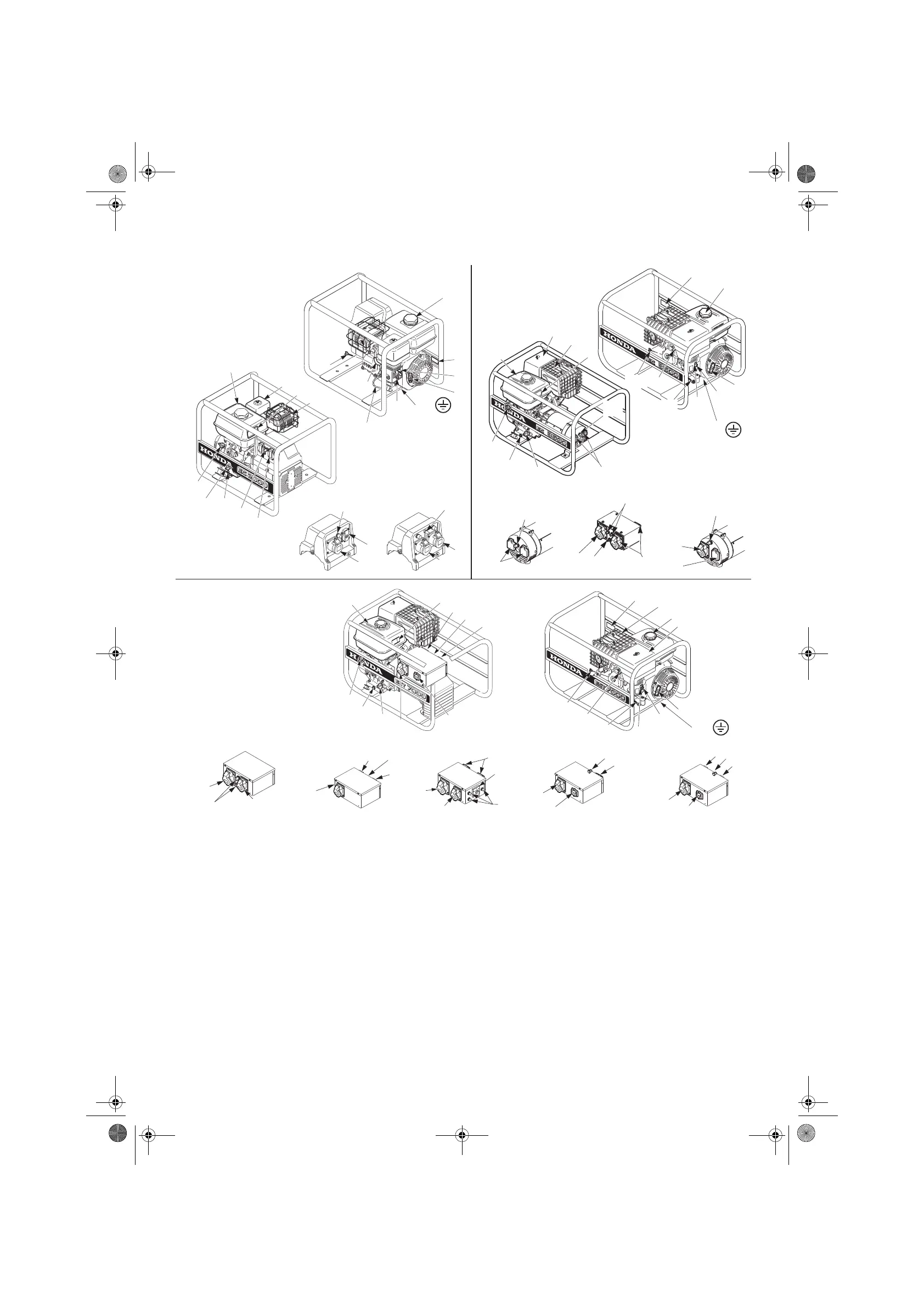
GENERAL DESCRIPTION
(The illustrations in this presentation are based on F, GV, GVW, types).
[1] Fuel tank cap [13] Engine oil drain plug
[2] Fuel tank [14] Engine switch
[3] Recoil starter grip [15] Voltage selector switch 115 / 230V, B type
[4] Fuel valve [16] Receptacles 230 V / 16 A (blue) B, IT types
[5] Choke lever [17] Receptacles 230 V / 16 A (black) F type, (blue) GV, GVW, IT types
[6] Earth braid [18] Receptacles 230 V / 10 A (black) W type
[7] Spark plug cap [19] Receptacles 115 V / 16 A (yellow) B type
[8] Oil filler cap / dipstick [20] Receptacles 115 V / 32 A (yellow) B type
[8’] Oil filler cap (choice of [8] or [8’] as required) [21] Receptacles 230 V / 16 A (blue) F, GV, GVW, RG types
[9] Air cleaner [22] Receptacles 400 V / 16 A (red ) F, GV, GVW, IT, RG types
[10] Label with list of specifications [23] Receptacles 230 V / 32 A (blue) IT, F types
[11] Muffler [24]
Earth terminal
[12] Thermal circuit breakers [A] “Serial number” Identification plate
[11]
[7]
[6]
[5]
[4]
[3]
[1]
[A]
[9]
[8-8']
[22]
[21]
[12]
[21]
[12]
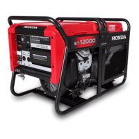
ECT7000 F
[12]
[16]
[12]
[22]
ECT7000 IT
[19]
[12]
[15]
[16]
[20]
EC5000B
[23]
[21]
[21]
[12]
EC5000
F,GV,GVW
EC5000 IT
[12]
[23]
[16]
[12]
[10]
[21]
[22]
[13]
[14]
[2]
[8-8']
[21]
[12]
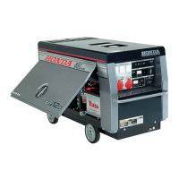
EC5000
ECT7000
[11]
[10]
[9]
[2]
[13]
[12]
[17-18]
[8-8’]
[14]
[4]
[3]
[5]
[A]
[6]
[7]
[1]
[8-8’]
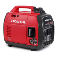
EC2000
[3]
[4]
[5]
[7]
[1]
[A]
[16]
[19]
[12]
[15]
[16]
[17]
[12]
[17]
[12]
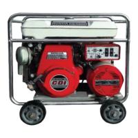
EC3600
[6]
[8-8']
GV, GVW
B
IT
[9]
[2]
[11]
[10]
[17]
[14]
[13]
[8-8']
[12]
[24]
[24]
[24]
[16]
[19]
[15]
[12]
[16]
[17]
B
IT
OM EC Serie_.book Page 3 Lundi, 12. mars 2012 9:27 09