RM7888A 7800 SERIES RELAY MODULE
32-00214—01 24
Normal sequence is used when the application requires
the burner flame to be modulated during the Run state.
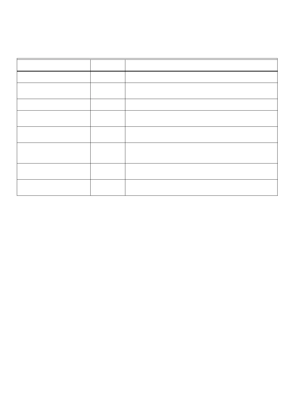
Table 9. DSI Configuration Operation Sequence States.
DSI State Name
Displayed
Text Purpose
Normal—Part 1 (Main Flame
Establishing Period [MFEP])
MAIN IGN
00:ss
Establish a Low Fire flame. Display shows elapsed time for Normal—
Part 1.
Normal—Part 2 (Main Flame
Establishing Period [MFEP])
MAIN IGN
00:ss
Allow for main valve operators to be placed into the normal operating
condition while at Low Fire position. Display shows elapsed time for
Normal—Part 2.
Normal—Part 3 (Run) RUN Allow normal operation to take place where a modulating control
provides the motor position signal.
High/Low Stepfire—Part 1 (Main
Flame Establishing Period
[MFEP])
MAIN IGN
00:ss
Establish a Low Fire flame. Display shows elapsed time.
High/Low Stepfire—Part 2 (Run) RUN Run with Low Fire flame while commanding Low Fire for an indefinite
time period. When the appropriate special function signals are present,
the sequence will advance into the HI (Run at High Fire) state.
Run—High RUN Run with a High Fire flame for an indefinite period. From this state, the
sequence can return to the Low Fire state upon command without
recycling. Commanded output state is the same as Normal—Part 3, but
special function signals are different.
OFF/ON Stepfire—Part 1 (Main
Flame Establishing Period
[MFEP])
MAIN IGN
00:ss
Establish a Low Fire flame. Display shows elapsed time.
OFF/ON Stepfire—Part 2 (Run) RUN Run with a high fire flame for an indefinite period. Commanded output
state is the same as Normal Part 3 but special function signals are
different.

 Loading...


