RM7888A 7800 SERIES RELAY MODULE
25 32-00214—01
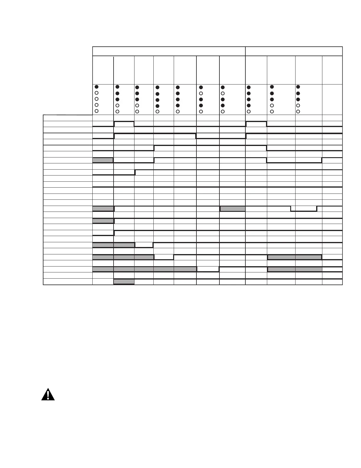
Fig. 21. RM7888A Relay Module Pilot Sequuence timing diagram.
High/Low Stepfire sequence is used when the application
requires the burner flame to be switched, on command,
between a Low Fire and a High Fire Run state.
Off/On Stepfire sequence is used when the application
requires the burner flame to be switched, on command,
between a Standby state and a Main Flame state.
Each DSI operating sequence has several states. See Table
9 for the state names, the text as shown on an S7800A
Keyboard Display Module, and a brief description of the
state purpose. All three sequences have the Standby state
in common.
The user of the RM7888A is responsible for
providing the correct signal to each special
function input terminal and must make sure that
safety is not compromised if an incorrect special
function input is applied.
Initiate State
The Initiate state will be entered when the RM7888A is
powered. The sequence will transition to the Standby state
after a ten second period. However, if any condition exists
that could prevent reliable operation of the RM7888A, the
sequence will remain in the Initiate state until the
condition is corrected. These conditions include the
detection of the loss of ac power, insufficient ac power
level, incorrect ac line frequency, and excess noise present
on the ac line. A ten second stabilization period occurs
after the condition is corrected before the sequence
transitions to the Standby state. Also, any condition that is
detected will remain annunciated for a minimum of five
seconds.
Standby State
Standby states for the DSI sequences are the same as
those for the Pilot sequences. See Pilot Configuration
Ignition Trials.
INPUT &
OUTPUT
SIGNALS
POWER
PILOT
FLAME
MAIN
ALARM
STANDBY
STANDBY-
PURGE
POWER POWER
PILOT
FLAME
PILOT
FLAME
PILOT RELIGHT
AFTER 10 SEC
WAIT FOR LOW
OFF FOR 5 SEC
RETURN
TO MAIN
TRAIN
FUEL ON
STATE
POWER
POWER
PILOT
FLAME
MAIN
POWER
PILOT
FLAME
MAINMAIN
MAIN
POWER
PILOT
FLAME
PILOT
IGNITION
MAIN
TRAIN
FUEL ON
0-INFINITE
TIME
BURNER
FUEL VALVE
OPEN-PILOT
TIMEOUT
BURNER
FUEL VALVE
OPEN-PILOT
TIMEOUT
LAST 5 TO
INFINITE
PILOT
RELIGHT
10 SEC
1ST 10 SEC
1ST 10 SEC
IGNITION- T10
PILOT- T8
MAIN- T9
AIR VALVE-T5
FLAME PROVEN- T21
ALARM- T3
MOTOR POSITION- T12-T15 L/H/MOD L L L L L LMOD MOD L
@ LOW FIRE INPUT- T18
LIMITS COMPLETE- T7
SF1 SPECIAL FUNCTION- T6
SF2 SPECIAL FUNCTION- T17
SF3 SPECIAL FUNCTION- T19
SF4 SPECIAL FUNCTION- T20
FLAME SENSED
POWER
2 TO 5 SEC.
(WITH 2-3 SEC.
AT LOW
STABILIZE)
DRIVE TO LOW
FIRE POSITION
POWER
POWER
PILOT
FLAME
MAIN
PILOT
FLAME
PILOT
FLAME
PILOT
FLAME
POWER
PILOT-
IGNITION
LAST 5-
INFINITE
SECONDS
RELEASE TO
MODULATION
PV Return and MV Lo Fire PV Return Only
M9497A
5 TO INFINITE
SEC
RUN: 0 TO
INFINITE SEC

 Loading...


