1 65-0120—1
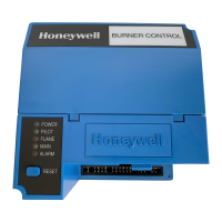
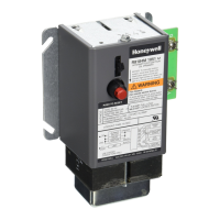
The Honeywell RM7838B is a microprocessor based
integrated burner control for industrial process semi-
automatically fired gas, oil, coal or combination of fuels
for single burner applications. The RM7838B consists
of a Relay Module, Subbase, Amplifier, Keyboard Dis-
play Module and Purge Card. Options include Personal
Computer Interface, DATA CONTROLBUS MOD-
ULE™, Remote Display Mounting, First-Out Expanded
Annunciator and software COMBUSTION SYSTEM
MANAGER
®
.
The RM7838B is programmed to provide a level of
safety, functional capability and features beyond the
capacity of conventional process control combustion
systems.
Functions provided by the RM7838B include auto-
matic modulated high fire and low fire proven purge,
burner pilot start up with pilot valve hold, a special
pilot valve hold from the Run condition, flame supervi-
sion, system status indication, system or self-diagnos-
tics and troubleshooting.
7800 SERIES
RM7838B Relay Module
L.Z. • Rev. 1-95 • ©Honeywell Inc. 1995
65-0120-1
■ Safety features:
— Combustion Interlock check.
— Closed loop logic test.
— Dynamic input check.
— Dynamic safety relay test.
— Dynamic self-check logic.
— Expanded safe-start check.
— High Fire Purge Switch test.
— Internal hardware status monitoring.
— Low Fire Purge Switch test.
— Tamper resistant timing and logic.
■ Access for external electrical voltage checks.
■ Application flexibility.
■ Communication interface capability via personal com-
puter utilizing MicroSoft
®
Windows™ software.
■ First out annunciation and system diagnostics provided by
2 row by 20 column Vacuum Fluorescent Display (VFD)
located within the local or remotely mounted Keyboard
Display Module.
■ First out expanded annunciation with 24 limit and inter-
lock Light Emitting Diodes (LEDs) (optional).
■ Five sequence information LEDs.
■ Five function Run/Test Switch.
■ Interchangeable plug-in flame amplifiers.
■ Local or remote annunciation of operation and fault
information.
■ Dependable, long-term operation provided by microcom-
puter technology.
■ Nonvolatile memory for retaining history files and se-
quencing status after loss of power.
■ Remote reset (optional).
■ Report generation (optional).
■ Burner controller data (optional):
— Sequence status.
— Sequence time.
— Hold status.
— Lockout/alarm status.
— Flame signal strength.
— Expanded annunciator status.
— Total cycles of operation.
— Total hours of operation.
— Fault history of six most recent faults:
• Cycles of operation at time of fault.
• Expanded annunciator data at time of fault.
• Fault message and code.
• Hours of operation at time of fault.
• Sequence status at time of fault.
• Sequence time at time of fault.
— Diagnostic information:
• Device type.
• Flame amplifier type.
• Flame failure response time.
• Manufacturing code.
• On/Off status of all line voltage digital inputs.
• Selected purge time.
• Software revision and version of RM7838B and
Keyboard Display Module.
• Status of configuration jumpers.
• Status of Run/Test switch.
• On/Off status of all line voltage digital outputs.
