24
5.2 Access control function
0....9
and
or
ID
5.3 Activate control functions/macros (RS-485 only)
5. Application in access control systems
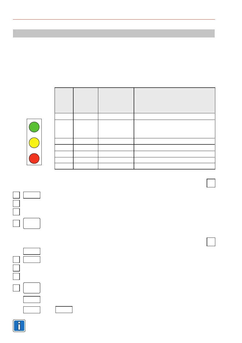
5.1 LED indication
The LEDs and the buzzer are controlled over a bus system. The definition for each is specified in the
main software and not at the reader.
At readers with Clock/Data interface the yellow LED lights permanently and can not be switched off.
At readers with RS-485 interface the yellow LED can be switched dark via software.
yellow
green
red
Color Basic After reading Meaning
condition a card or after
a keystroke
yellow on Operation / ready to read
off Device is idle
PIN-Code or door code entry is active
(only possible with RS-485 interface)
green on Permanently released
red on Permanently blocked
green on Door release
red on ID card not authorized
red blinking Read error
yellow
possible
possible
Enter PIN or door code (RS-485 only)
Hold the data carrier in the reading field
Press the “X” button
0....9
3
Enter the function number (macro number)
Confirm with the “OK” or the “X” button.
Enter PIN or door code
0....9
and
or
Hold the data carrier in the reading field
ID
r
r
or
For more informations see Supplementary Functions IQ MultiAccess
(P32205-46-0G0-xx)
""
Operating Instructions mifare/DESFire EV1 reader "Accentic" with/without keypad
 Loading...