BCU 370 · Edition 01.19 34
Function
3.4.5 Network technology
All devices are connected in a bus structure (line). Up to
32 subscribers (masters or slaves) can be connected in
a single segment. The beginning and end of each seg-
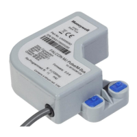
ment is fitted with an active bus terminator. Both bus
terminators must have a permanent power supply to
ensure error-free operation. The power supply for the
bus terminator is provided by the BCU. The bus termi-
nator can be connected in the bus connection plug.
If more than 32 subscribers are implemented or if there
is a need to expand the network area, repeaters (ampli-
fiers) must be used to link the individual bus segments.
3.4.6 Configuration
When planning a PROFIBUS DP system, unit-specific pa-
rameters of each subscriber are to be taken into account.
To allow for simple and standardized planning, the param
-
eters of the BCU..B1 have been summarized in a so-called
device master data file (GSD). The file structure is standard-
ized so that it can be read by the planning devices of differ-
ent manufacturers.
The GSD file can be downloaded from www.docuthek.
com, once you have registered. The steps required to copy
the file are described in the instructions for the automa-
tion system.
3.4.7 Bus communication
Input bytes (BCU ➔ master)
Bit Byte 0 Byte 1 Byte 2 Byte 3
0 Burner operation
Reserved
See table on page
79 (Status and fault messages
for PROFIBUS DP)
0–25.5 µA of the burner
255 steps
1
2 Fault lock-out
3 Controlled air flow
4
Open position
reached*
5
Closed position
reached*
6 ON
7 Manual mode
* Only on BCU 370..B13, three-point step control via PROFIBUS DP
Output bytes (master ➔ BCU)
Bit Byte 0
0 Reset
1 Start-up
2 Controlled air flow
3
4
5
6 Open*
7 Close*
* Only on BCU 370..B13, three-point step control via PROFIBUS DP
▼
 Loading...
