BCU 460, BCU 465 · Edition 11.19 10
Application
1.1.3 Staged control
VAS VAG
V1
V2
V3
UVS
VAS 1
BCU 460..F1
60 61 62 65 66
22
3 6
µC
81
82
95
96
35
2
Process control (PCC)
P
4
A
1
Start
1
HT
40 41
BVA
IC 40
4
12
16
DI 1
7
DI 2
M
µC
FCU 500 PLC
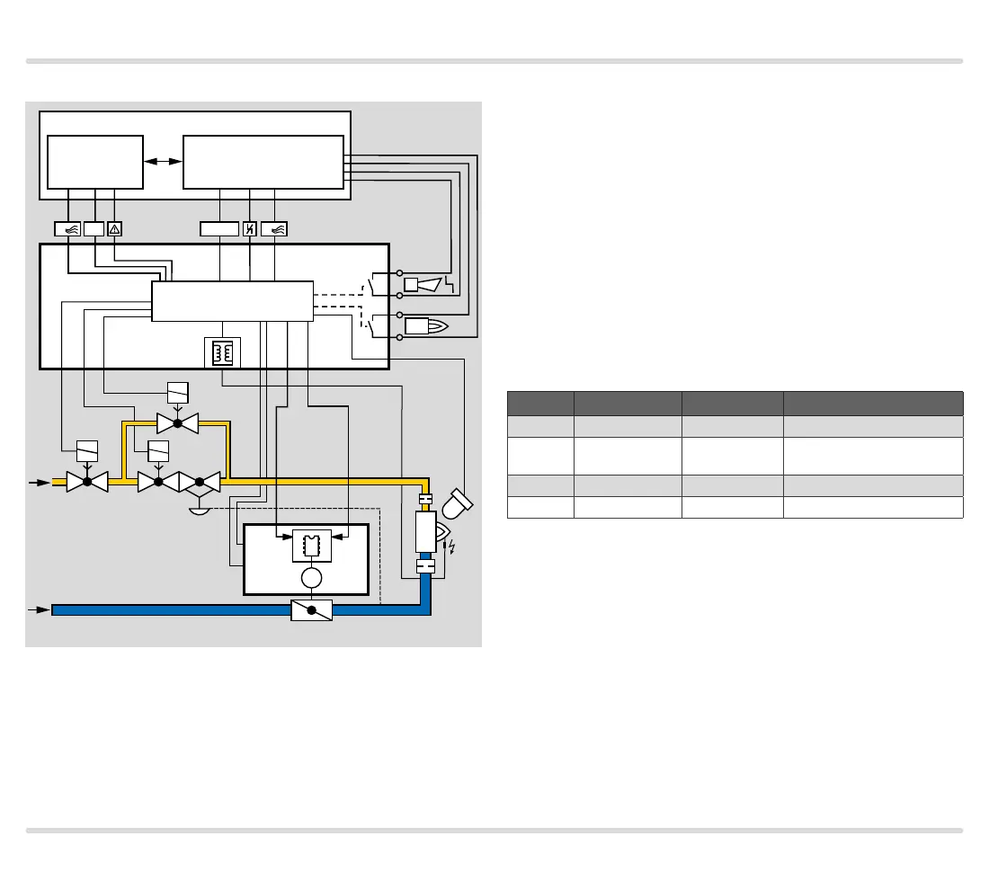
The central control system starts the pre-purge. Input
DI2 is activated via the output at terminal 66 of the
BCU and the butterfly valve BVA is set to the pre-purge
position.
In the event of a temperature demand, the burner con-
trol unit BCU activates input DI1 via the output at ter-
minal 65 and moves the butterfly valve to the ignition
position (condition: the IC40 must have reached the
ignition position on the instant of ignition). The burner
starts.
The burner application “Burner 1 with pilot gas” (pa-
rameter A078=1) is selected so that the burner can be
started with a limited start fuel flow rate.
To activate the high-fire rate, DI2 is actuated via the air
valve output at terminal66 of the BCU.
The butterfly valve moves cyclically between the high-
fire and low-fire rate position, see page110 (Operat-
ing mode 11).
DI 1/V1 DI 2/Air valve IC 40 position Valve position
Off Off closed Closed
On Off low
Ignition position/Low-fire
rate
On On middle High-fire rate
Off On high Pre-purge
 Loading...