BCU 460, BCU 465 · Edition 11.19 11
Application
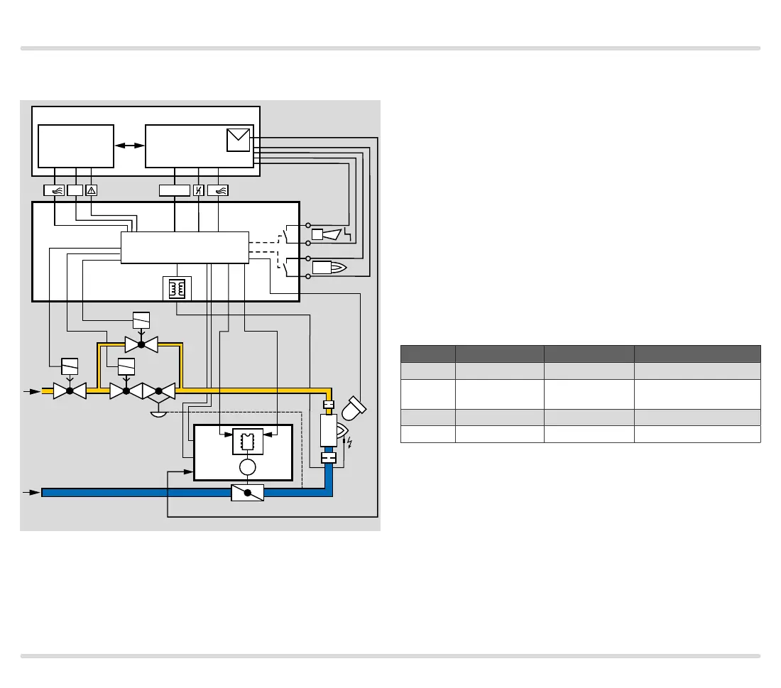
1.1.4 Modulating control with defined ignition
position
VAS VAG
V1 V2
V3
UVS
VAS 1
BCU 460..F1
60 61 62 65 66
22
3 6
µC
81
82
95
96
35
2
Process control (PCC)
P
4
A
1
Start
1
HT
40 41
BVA
IC 40
4
12
16
DI 1
7
DI 2
M
µC
18
IN
mA
FCU 500 PLC
The central control system starts the pre-purge. Input
DI2 is activated via the air valve output of the BCU and
the butterfly valve BVA is set to the pre-purge position.
In the event of a temperature demand, the burner con-
trol unit BCU activates input DI1 via the output at ter-
minal 65 and moves the butterfly valve to the ignition
position (condition: the IC40 must have reached the
ignition position on the instant of ignition). The burner
starts.
The burner application “Burner 1 with pilot gas” (pa-
rameter A078=1) is selected so that the burner can be
started with a limited start fuel flow rate.
During operation, the BCU activates DI1 and DI2 using
outputs 65 and66. This enables the analogue input IN
on the actuator IC40. Depending on the capacity de-
mand of the temperature controller, the butterfly valve
BVA moves steplessly between the low-fire rate and the
high-fire rate to the position specified by the analogue
input IN, see page110 (Operating mode 27).
DI 1/V1 DI 2/Air valve IC 40 position Valve position
Off Off closed Closed
On Off low
Ignition position/Low-
fire rate
On On analogue chart 1 In acc. with chart 1
Off On high Pre-purge/High-fire rate
 Loading...