C6097 · Edition 01.19 2
▼
= To be continued
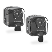
Gas pressure switch C6097..........................1
Contents ............................................2
1 Application ........................................3
1.1 Use .................................................4
1.1.1 CE approved pressure switches .......................4
1.1.2 FM approved and UL listed pressure switches........4
1.2 Application examples ..............................5
1.2.1 Low gas pressure monitoring .........................5
1.2.2 Differential pressure monitoring . . . . . . . . . . . . . . . . . . . . . .5
1.2.3 Systems leak tightness check .........................5
1.2.4 Air line with minimum pressure and flow monitoring .6
1.2.5 Low and high gas pressure protection device.........6
2 Certification .......................................7
2.1 EU certified ........................................ 7
2.2 FM approved....................................... 7
2.3 UL listed ........................................... 7
2.4 Overview of product approvals .................... 7
3 Function ...........................................8
3.1 Vent limiter .........................................8
3.2 Positive pressure measurement ...................9
3.3 Negative pressure measurement ..................9
3.4 Differential pressure measurement ...............9
3.5 Connection diagram ..............................11
3.5.1 Blue pilot lamp for 230 V AC or 110/120 V AC .......11
3.5.2 Red/green pilot LED for 24 V DC/AC or 110 –
230 V AC ....................................................11
3.6 Wiring .............................................12
4 Project planning information . . . . . . . . . . . . . . . . . . . . .13
4.1 Installation ........................................13
4.2 Ports ..............................................14
4.2.1 CE certified pressure switches ...................... 14
4.2.2 UL, FM certified pressure switches .................15
4.3 Resetting pressure switches with manual reset ..16
5 Accessories .......................................17
5.1 Fastening set with screws, U-shape bracket .....17
5.2 Connecting set ...................................17
5.3 Restrictor orifice ..................................17
5.4 Standard socket set...............................18
5.5 Standard coupler plug ............................18
5.6 Pilot lamp set, red or blue .........................18
5.7 LED set, red/green................................19
5.8 Cover for auto reset ...............................19
5.9 Cover for manual reset............................19
5.10 Weather protection cover ...................... 20
6 Technical data . . . . . . . . . . . . . . . . . . . . . . . . . . . . . . . . . . . . 21
6.1 General............................................21
6.2 EU certified pressure switches ...................21
6.3 UL, FM certified pressure switches ..............22
6.4 Adjusting range, switching hysteresis ............22
6.4.1 CE certified pressure switches ......................22
6.4.2 UL, FM certified pressure switches .................23
6.5 Dimensions .......................................24
6.5.1 EU certified pressure switches......................24
6.5.2 UL, FM certified pressure switches .................25
6.6 Converting units ..................................26
7 Maintenance cycles...............................26
Feedback ...........................................27
For more information ...............................27
Contents
 Loading...