C7961E,F DYNAMIC SELF-CHECK ULTRAVIOLET FLAME DETECTOR
65-0267-09 10
Removing Detector from Sight Pipe
(Refer to Fig. 8)
Loosen the three screws holding the mounting flange; rotate
the detector slightly so the screws clear the slots in the back
section of the flange; separate the flange; and pull off the back
section (with the UV sensor).
NOTE: The detector is free when the collar is unscrewed;
do not drop it.
Procedure for Zero Meter Reading
1. Replace the plug-in amplifier. Then recheck the flame
signal.
2. Replace the coil and shutter assembly (see Installation
Instructions 66-1169). Then recheck the flame signal.
3. If you cannot yet obtain a meter reading, replace the
detector.
IMPORTANT
At the completion of Troubleshooting, be sure to per-
form the Adjustments and Checkout procedures.
SERVICE
Electrical shock hazard.
Can cause serious injury or death.
Open the master switch to disconnect power before
removing or installing the detector or its cover. More
than one disconnect can be involved.
Periodic Maintenance
1. Clean the viewing window (or focusing lens) when nec-
essary. Remove the detector (see Troubleshooting sec-
tion) and use a clean cloth over the eraser end of a
pencil. Do not remove the window (or lens) to clean it. If it
is broken or damaged or it is coated with a substance
that cannot be removed, replace it (see Fig. 13).
2. Keep the flame detection system adjusted for the
smoothest, most reliable operation as recommended by
the burner manufacturer.
3. Replace viewing window only when necessary to obtain
proper operation.
Removing Detector Cover (All
Models):
1. Open the Master Switch.
2. Unscrew the four captive cover screws (Fig. 7) and care-
fully slide off the cover.
NOTE: These bolts are removable. Put them in a safe
place to avoid losing them.
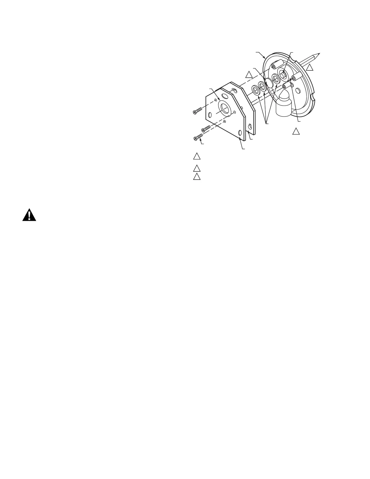
Fig. 12. Replacing quartz viewing
window or focusing lens.
Replacing Quartz Viewing Window
(or Focusing Lens)
C7961E (Fig. 12)
IMPORTANT
Use quartz window or lens. Ordinary glass absorbs or
filters out ultraviolet radiation.
1. Open the master switch; remove the detector from the
sight pipe and remove the detector cover. (See appropri-
ate sections.)
2. Loosen the three screws holding the back section of the
mounting flange to the faceplate. Carefully remove and
keep together the three screws, the gray
fiber-neoprene gasket, the red rubber washer, and the
back section of the mounting flange.
NOTE: If the viewing window (with its rubber mounting
gaskets) is stuck to the mounting flange, skip
step 3.
IMPORTANT
Be very careful not to kink or otherwise damage the
flexible shutter.
3. Using the eraser end of a pencil, push out the viewing
window (with its rubber mounting gaskets) from the
inside of the faceplate.
4. Insert one rubber mounting gasket into the window aper-
ture in the faceplate.
5. Insert the new quartz viewing window (or focusing lens)
into the window aperture with either side toward the
flame.
6. Insert two rubber mounting gaskets (only one gasket
when replacing a focusing lens) into the aperture.
7. Put the back section of the mounting flange, red rubber
washer, and fiber-neoprene gasket in place on the face-
plate, and securely tighten the three mounting screws.
1
3
1
2
2
3
FACEPLATE
PENCIL
114372 (20 PSI) OR 122748 (50 PSI)
QUARTZ VIEWING WINDOW (OR 124204
QUARTZ FOCUSING LENS, 20 PSI)
114638 RED RUBBER
WASHER (BETWEEN
GASKET AND
FLANGE)
MOUNTING
SCREWS (3)
WINDOW
APERTURE
114465 RIBBER
MOUNTING
GASKETS (3)
BACK SECTION OF
MOUNTING FLANGE
VIEWING WINDOW CAN BE REPLACED WITH EITHER SIDE TOWARD
THE FLAME.
ONLY ONE GASKET ON EACH SIDE OF THE FOCUSING LENS.
REMOVE THE THREE MOUNTING SCREWS AND MOVE THE COIL
AND SHUTTER ASSEMBLY OUT OF THE WAY TO PUSH OUT THE
VIEWING WINDOW.
M10130B
120739 FIBER-NEOPRENE GASKET
 Loading...