C7961E,F DYNAMIC SELF-CHECK ULTRAVIOLET FLAME DETECTOR
3 65-0267-09
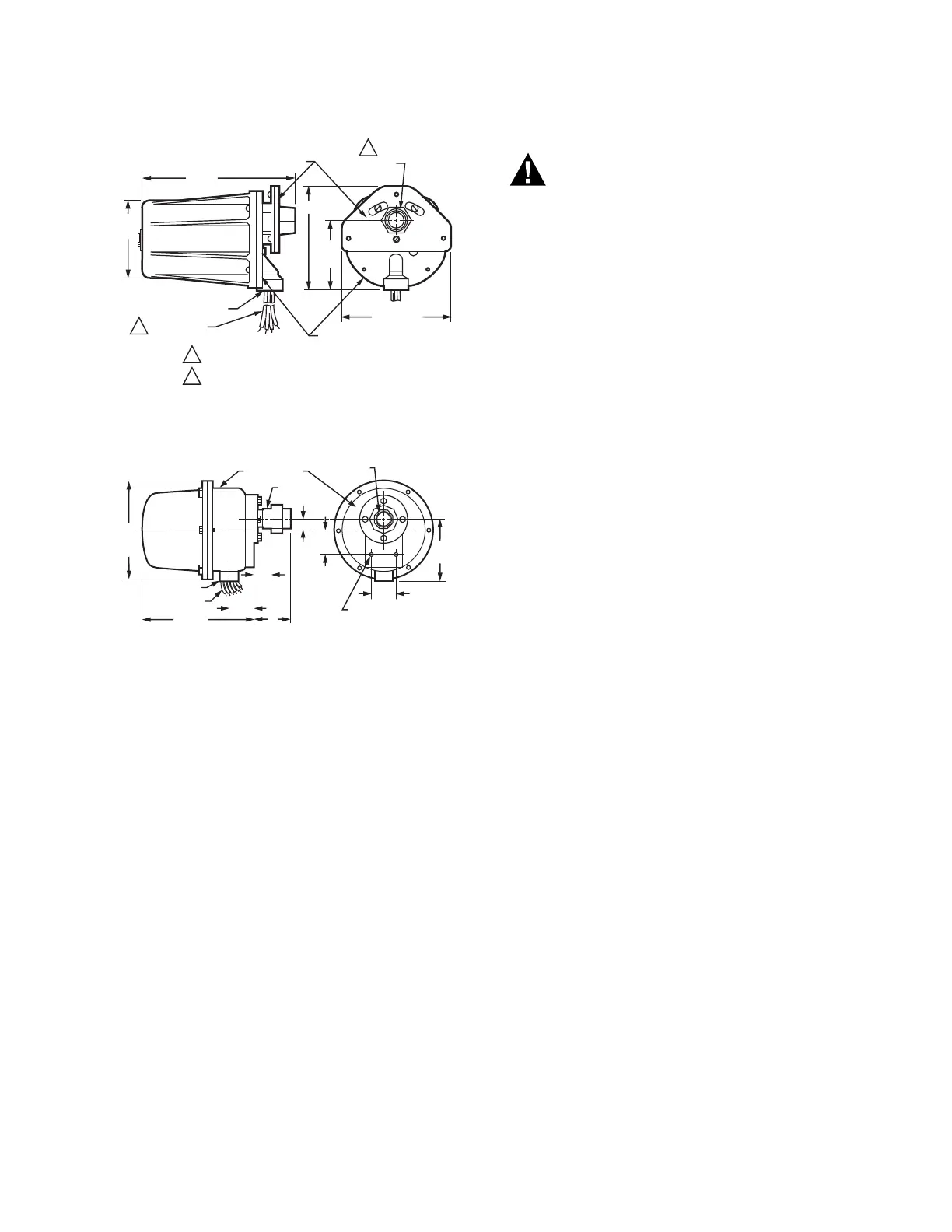
Fig. 1. Dimensions of C7961E in inches. (mm).
Fig. 2. Dimensions of C7961F in inches. (mm).
Accessories:
C7961E:
118367A Swivel Mount.
123539 Antivibration Mount.
122748 Quartz Viewing Window, rated for 50 psi
(345 kPa).
124204 Quartz Focusing Lens, rated for 20 psi (138 kPa);
increases the detector-sensed ultraviolet radiation.
120934 Mounting Flange, aluminum, with 3/4 inch NPT
internal threads for attaching to sight pipe.
124198 Mounting Flange, aluminum, with 1 inch NPT inter-
nal threads for attaching to sight pipe.
INSTALLATION
When Installing this Product...
1. Read these instructions carefully. Failure to follow them
could damage the product or cause a hazardous condi-
tion.
2. Check the ratings given in the instructions and on the
product to make sure the product is suitable for your
application.
3. Installer must be a trained, experienced flame safeguard
service technician.
4. After installation is complete, check out product opera-
tion as provided in these instructions.
Electrical shock hazard.
Can cause serious injury or death.
Disconnect power supply before beginning installation
to prevent electrical shock and equipment damage.
More than one disconnect may be involved.
NOTICE: Per industry standards, a conduit seal or a cable
type that is sealed is required to be installed in a device
that can result in flammable gas or flammable liquid flow
through a conduit or cable to an electrical ignition source
in the event of a seal leakage.
IMPORTANT
1. Do not connect these detectors to non-Honeywell
manufactured controls (primaries, programmers, mul-
tiburner systems, and burner management systems).
Unsafe conditions could result.
2. All wiring must be NEC Class 1 (line voltage).
3. Voltage and frequency of the power supply connected
to this detector must agree with the values marked on
the detector.
4. Sight the detector so it does not respond to ignition
spark.
5. On multiburner installations, each detector must
respond only to the flame of the burner it is supervis-
ing.
Proper flame detector installation is the basis of a safe and
reliable flame safeguard installation. Refer also to the burner
manufacturer instructions. Carefully follow all instructions for
the best possible flame detection application.
Basic Requirements
The combustion flames of most carbon-based fuels emit
sufficient ultraviolet radiation to enable the C7961 Solid State
(Purple Peeper) Ultraviolet Flame Detector to prove the
presence of a flame in a combustion chamber. The detector is
mounted outside the combustion chamber with its mounting
flange or union threaded to one end of a sight pipe inserted
through the wall of the combustion chamber. The ultraviolet
sensing tube in the flame detector sights the flame through the
pipe.
When a flame is present, the C7961 senses the ultraviolet
radiation emitted. The C7961 then produces a signal that is
sent to the amplifier in the flame safeguard control. The
amplified signal pulls the flame relay into the control to allow
proper system operation.
Because it is necessary for the C7961 to actually see the
flame, it is best to locate the detector as close to the flame as
physical arrangement, temperature, and other restrictions
permit. These restrictions are described in detail in the
following paragraphs.
Determine Location
Before beginning the actual installation, determine the best
location for mounting the detector. Carefully consider the
factors discussed in this section before deciding on the
location.
MOUNTING FLANGE
1/2–14 NPSM
LEADWIRES
FACEPLATE
3/4–14 NPT
M24000B
3-3/4
(95)
7-7/32
(183)
5-1/8 (130)
3-7/16
(87)
5-1/4 (133)
1
1
2
2
C7961E1014, E1022 1 INCH NPT MODELS
C7961E1022, E1030 CONNECTOR MODELS.
M1963A
FACEPLATE
PIPE
UNION
8
(203)
DIA.
1/2-14 NPT
LEADWIRES
9 (229)
2
(51)
5
(127)
1-11 1/2 NPT
2-1/16
(52)
1-1/2
(38)
5/16-18 UNC-2B BY
7/16 (11) DEEP
MOUNTING HOLES (2)
2 (51)
1 (25)
3
(76)
 Loading...