C7961E,F DYNAMIC SELF-CHECK ULTRAVIOLET FLAME DETECTOR
65-0267-09 4
Temperature
Install the C7961 where the ambient temperature (outside the
case) stays within the ambient operating temperature ratings.
To keep the C7961 below its maximum rating, it may be
necessary to add additional insulation between the wall of the
combustion chamber and the detector. A shield or screen can
be added to reflect radiated heat away from the detector. If the
detector continues to get too hot, cooling is necessary. Refer to
the Sight Pipe Ventilation section.
Vibration
If the C7961 is subject to excessive vibration, use a special
123539 Antivibration Mount. If you use this mount, install it
before you position and sight the detector.
Clearance
Make sure there is enough room to easily mount the sight pipe,
detector, and all required fittings, and to remove the detector
for troubleshooting and servicing.
Radiation Sources (Other than
Flame)
Examples of radiation sources (other than flame) that could
actuate the detection system:
Ultraviolet sources:
Hot refractory above 1800°F (982°C).
Spark:
— Ignition transformers.
— Welding arcs.
— Lightning.
Welding flames.
Bright incandescent or fluorescent artificial light.
Solar radiation.
Gas lasers.
Sun lamps.
Germicidal lamps.
Bright flashlight held close to the sensing tube.
Gamma ray and X-ray sources:
The C7961 is immune to x-ray exposure.
Except under unusual circumstances, none of these sources
except hot refractory and ignition spark would be present in or
near the combustion chamber.
The detector can respond to hot refractory above 1800°F
(982°C) if the refractory surface represents a significant
percentage of the detector field of view. If the temperature of
the hot refractory causes the flame relay (in the flame
safeguard control) to pull in, re-aim the sight pipe so the
detector views a cooler area of the refractory.
Ignition spark is an intense source of ultraviolet radiation.
When installing the detector, make sure it does not respond to
ignition spark.
Single Burner Requirements
The detector must have an unobstructed view of a steady part
of the flame it is supervising. This requires a proper sighting
angle and minimized ultraviolet radiation attenuation effects.
However, when supervising only one burner, sighting
requirements are simplified.
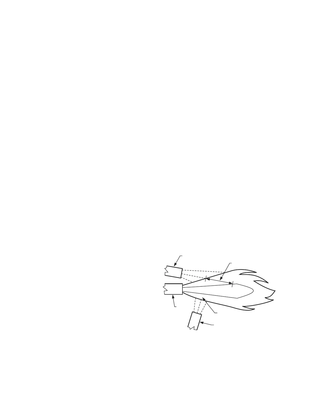
Sighting Angle (Fig. 3)
The first 30 percent of a flame closest to the burner nozzle (the
flame root) emits the most ultraviolet energy. Also, if the
detector sights the flame at an angle instead of
perpendicularly, it views more flame depth. Therefore, the best
sighting angle is nearly parallel to the axis of the flame,
permitting the detector to view a large portion of the first 30
percent of the flame closest to the burner nozzle, as illustrated
in Fig. 3.
Low angle sighting permits the detector to view a greater depth
of flame, thus reducing the effects of instabilities in the flame
pattern. Also, the environment near the burner nozzle is
usually cleaner than at any other part of the combustion
chamber. This provides a clearer line of sight and can keep the
viewing window cleaner, thus reducing the maintenance
required.
Fig. 3. Detector sighting angle.
NOTE: When possible, it is desirable to tilt the detector
and sight pipe downward to prevent the buildup
of soot in the pipe or on the viewing window.
DETECTOR IN GOOD
SIGHTING POSITION
(LOW ANGLE SIGHTING)
FLAME DEPTH-
ANGLE VIEW
BURNER
NOZZLE
DETECTOR IN POOR
SIGHTING POSITION
FLAME DEPTH-
PERPENDICULAR VIEW
UNBURNED FUEL
M1956A
 Loading...