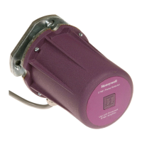
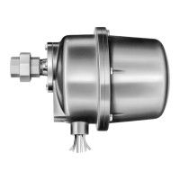
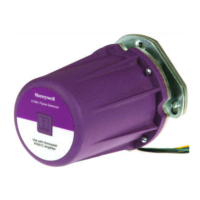
C7961E,F DYNAMIC SELF-CHECK ULTRAVIOLET FLAME DETECTOR
9 65-0267-09
Table 1. Flame Signal.
a
Shutter operation of the C7961 may cause fluctuations in the voltage reading. Read the average stable voltage, disregarding the
peaks.
b
Shutter operates at 3 Hz rate, the 7800 Series conducts an additional shutter test every 5 seconds..
2. Start the burner and run through the Ignition period. Igni-
tion spark should occur, but the flame LED must
not light. The flame signal should not be greater than
0.25 Vdc.
3. If the flame relay does pull in, reposition the detector far-
ther from the spark, or relocate/resight the detector to
eliminate/reduce the detector response to reflected UV
radiation. It may be necessary to construct a barrier to
block the ignition spark from the detector view. Continue
adjustments until the flame signal due to ignition spark is
less than the flame signal values indicated in step 2.
Response to other Ultraviolet
Radiation Sources
Some sources of artificial light produce small amounts of
ultraviolet radiation. Under certain conditions, an ultraviolet
detector responds as if it is sensing a flame. Do not use an
artificial light source to check the response of an ultraviolet
flame detector. To check for proper detector operation, conduct
flame failure response tests under all operating conditions.
Weld the Sight Pipe
When the flame signal is acceptable after all adjustments are
made, remove the detector and weld the sight pipe in its final
position. (If you are using a swivel mount, the pipe may be
already welded.) Then reinstall the detector.
Final Checkout
Before putting the burner into service, check out the installation
using the Checkout procedures in the Instructions for the
appropriate flame safeguard control. After completing the
Checkout, run the burner through at least one complete cycle
to verify correct operation.
IMPORTANT
Do not put the system into operation until all Checkout
tests in the Instructions for the appropriate flame safe-
guard control and any others specified in the burner
installation instructions are satisfactorily completed.
TROUBLESHOOTING
Electrical shock hazard.
Can cause serious injury or death.
Open the master switch to disconnect power before
removing or installing the detector or its cover. More
than one disconnect may be involved.
Equipment Required
A volt-ohm meter with a minimum sensitivity of one
megohm/volt and a zero to five or ten Vdc scale is suggested.
When the Keyboard Display Module is included with the
control, a flame signal displays on the module.
For replacement parts, see Specifications section.
Unsatisfactory Flame Signal
If a satisfactory flame signal (see Table 1) cannot be obtained
while adjusting the sighting position of the detector, follow
these procedures. If you encounter other problems in the
system, refer to the Troubleshooting section in the instructions
for the appropriate flame safeguard control.
NOTE: For instructions to replace the viewing window,
see
the Service section.
Troubleshooting Procedures
First perform the Preliminary Inspection. Then follow the
applicable procedures for either a low meter reading or a zero
meter reading. After reinstalling the detector or replacing its
cover, recheck the meter reading. To try to obtain the proper
flame signal, adjust the position of the detector. If you complete
all of the procedures and yet cannot obtain a proper flame
signal, replace the detector.
Preliminary Inspection
1. Check for the proper line voltage. Make sure the master
switch is closed, connections are correct, and power
supply is of the correct voltage and frequency.
2. Check the detector wiring for defects:
a. Incorrect connections.
b. Wrong type or size of wire.
c. Deteriorated wire.
d. Open circuits.
e. Short circuits.
f. Leakage paths caused by moisture, soot, or dirt.
3. With the burner running, check the temperature at the
detector. If it exceeds 175°F (79°C):
a. Add additional insulation between the wall of the
combustion chamber and the detector.
b. Add a shield or screen to reflect radiated heat away
from the detector, or
c. Add cooling (refer to Sight Pipe Ventilation and
Accessories sections).
Flame Detector
Plug-in Flame
Signal Amplifier Flame Safeguard Control(s)
Minimum
a
Acceptable Steady
Voltag e (Vdc )
Maximum Expected
Voltag e (Vdc )
C7961E,F R7851C Dynamic
Self-Check
a,b
7800 Series or R7140 1.25 5.0
 Loading...