C7961E,F DYNAMIC SELF-CHECK ULTRAVIOLET FLAME DETECTOR
65-0267-09 8
ADJUSTMENTS AND
CHECKOUT
For initial burner lightoff, consult the burner manufacturer
instructions or the flame safeguard control instructions.
Adjust Detector Sighting
With the flame detector installed and the burner running, adjust
the sighting position of the detector for optimum flame signal.
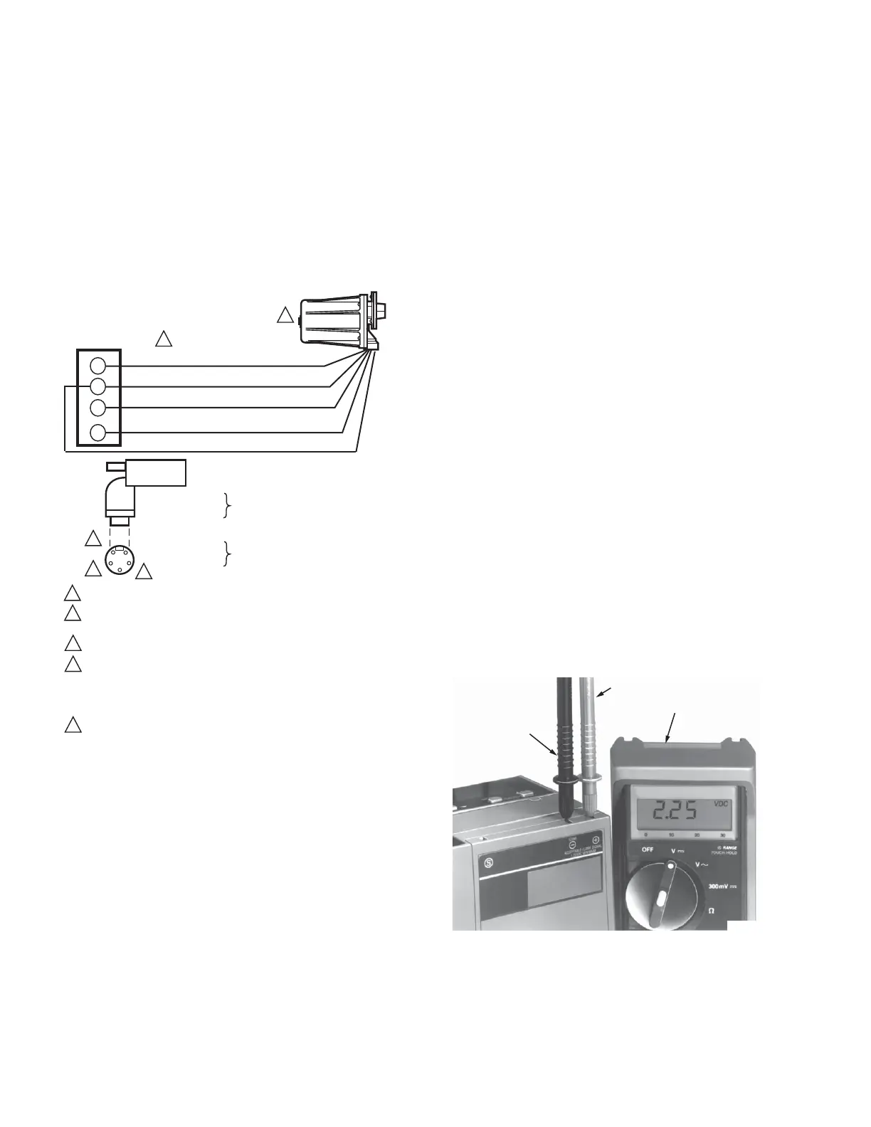
Fig. 10. Wiring diagram for C7961E,F Detectors
with 7800 Series Flame Safeguard
controls.
It is suggested that a volt-ohm meter with a minimum sensitivity
of one megohm/volt and a zero to five or ten Vdc scale be used
for R7861 Amplifier flame signal measurements. Measure the
flame signal as illustrated in
Fig. 10. Be careful to make the proper connections of
positive (red) meter lead to positive (+) control jack and
negative (black) meter lead to negative (-) or (-Com) jack with
7800 Series controls. When the 7800 Series control has a
Keyboard Display Module, a zero to five Vdc voltage is
displayed on the module.
NOTES:
1. The shutter operation could cause fluctuations in
the voltage reading. Read the average stable read-
ing, disregarding the peaks.
2. The flame signal must be steady (or stable as
described in note 1).
Move the detector and sight pipe around to sight the flame
from various positions and angles. Try to get a maximum
steady (or stable) reading on the meter that is above the
minimum acceptable voltage listed in Table 1.
Measure the flame signal for the pilot alone, the main burner
flame alone, and both together (unless monitoring only the pilot
flame when using an intermittent pilot, or only the main burner
flame when using direct spark ignition). Also measure the
flame signal at low and high firing rates and while modulating in
between (as applicable). With the detector in its final position,
all required flame signals must be steady
(or stable) and as specified in Table 1. If you cannot obtain the
proper signal, refer to the Troubleshooting section.
Pilot Turndown Test
When the detector is used to prove a pilot flame before the
main fuel valve(s) can be opened, perform a Pilot Turndown
Test before welding the sight pipe into position. Follow the
procedures in the flame safeguard control instructions and in
the burner manufacturer instructions.
Ultraviolet Response Tests Ignition
Spark Response Test
Test to be sure that ignition spark is not actuating the flame
relay in the flame safeguard control.
1. Close the pilot and main burner manual shutoff valves.
Fig. 11. Measuring voltage flame signal
with 7800 Series controls.
F
G
L1
L2
1
2
3
4
5
3
4
1
2
1
2
3
4
5
C7961
C7961
WIRING MUST BE NEC CLASS 1.
7800 SERIES
FLAME SAFEGUARD
CONTROL
TERMINAL STRIP
BLUE (F)
YELLOW (G)
WHITE
BLACK
(L1)
(L2)
M34216A
AN R7852C DYNAMIC SELCHECK AMPLIFIER MUST BE USED.
VOLTAGE AND FREQUENCY RATING OF THE C7961 MUST MATCH THE
POWER SUPPLY OF THE FLAME SAFEGUARD CONTROL.
KEYED CONNECTOR ALLOWS CONNECTION IN ONLY ONE POSITION.
C7961E1022 OR E1030 REFERENCE MOLEX WOODHEAD 1R5006A20A120
(FORMERLY BRAD HARRISON CONNECTOR TYPE 41310). MATING
CONNECTOR CAN BE 105000A01F0302 or 105000A01F0602) (FORMERLY
BRAD HARRISON CONNECTOR TYPE 41306N OR 41307N) (NOT
SUPPLIED BY HONEYWELL).
NOTE C7961 TERMINAL 4 IS CONNECTED TO ELECTRICAL GROUND.
5
TERMINAL 1-(L1)
TERMINAL 5-(L2)
TERMINAL 4-
TERMINAL 2-(F)
TERMINAL 3-(G)
POWER
INPUT
FLAME
OUTPUT
ELECTRICAL
GROUND
GREEN
(GND)
NEGATIVE (-)
METER LEAD
POSITIVE (+)
METER LEAD
ONE
MEGOHM/VOLT
METER
M7383C
 Loading...