C7961E,F DYNAMIC SELF-CHECK ULTRAVIOLET FLAME DETECTOR
65-0267-09 6
Mount Sight Pipe
Thread one end of the pipe to fit the mounting flange, union, or
required coupling. Cut the pipe to the desired length (as short
as practical) and at an angle so it fits flush with the wall of the
combustion chamber. Tack weld the pipe to the wall in a trial
position. Do not weld the sight pipe permanently in place until
after completing the Adjustments and Checkout.
NOTE:If you use 118367A Swivel Mount and you are positive
about the location and sighting angle, you can permanently
weld the pipe.
Install Fittings
In some cases, the sight pipe does not directly fit the C7961
mounting flange or union. Also, it may be desirable or
necessary to ventilate the sight pipe. You may also want to use
a swivel mount or an antivibration mount. Each of these cases
can require additional fittings.
Reducer
For sight pipes of larger diameter than the mounting flange
connector or union, install a reducer as illustrated in Fig. 5. The
reducer requires a close nipple with 3/4 in. NPT external
threads:
Sight Pipe Ventilation
It may be necessary to ventilate the sight pipe to cool the
detector or to clear a viewing path through UV radiation
attenuating material.
For a negative pressure combustion chamber, drilling a few
holes in the section of the sight pipe outside of the combustion
chamber allows air at atmospheric pressure to flow through the
sight pipe and into the chamber. A perforated pipe nipple
between the sight pipe and the detector can also be used.
For a positive pressure combustion chamber, connect a supply
of pressurized air from the burner blower to flow through the
sight pipe and into the chamber. The air pressure must be
greater than the chamber pressure.
Swivel Mount
To facilitate proper flame sighting, use 118367A Swivel Mount
(ordered separately). The swivel mount requires a reducer of
the proper size to mount it onto the sight pipe. It also requires a
one-inch close nipple for mounting to a C7961 with a
one-inch connector. (For 118367A Swivel Mount mounting
details, refer to 60-0361.)
Antivibration Mount
The detector withstands normal burner vibration. If the
vibration is excessive, 123539 Antivibration Mount is available.
(For mounting details, see form 60-0361.) If you use this
mount, install it before positioning and sighting the detector.
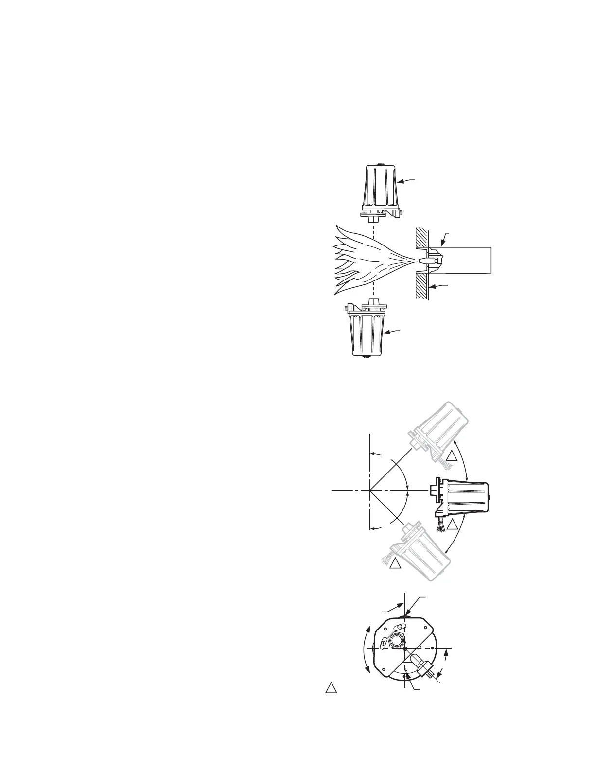
Mount the Detector (Fig. 5-8)
Mount the detector onto the sight pipe, reducer, or other fitting
(see Fig. 5-8).
The C7961 Self-Checking Flame Detectors incorporate an
oscillating shutter mechanism and, therefore, require special
consideration for mounting positions other than vertically
sighting downward or upward, as illustrated in Fig. 6. The
C7961 has notch and arrow indicators (see Fig. 7) on the
faceplate to facilitate mounting in positions other than those
shown in Fig. 6. The notch and arrow must be vertically aligned
with the notch in the up position and the arrow pointing
downward (see Fig. 7). The C7961 must be mounted with the
conduit opening located approximately 45 degrees below the
horizontal (see Fig. 7).
Fig. 6. Vertical mounting of C7961E.
Fig. 7. C7961 mounting positions.
C7961 SIGHTING
VERTICALLY DOWNWARD
BURNER
COMBUSTION
CHAMBER WALL
C7961 SIGHTING
VERTICALLY UPWARD
M34213
1
M34214
VERTICAL
PLANE
NOTCH AND ARROW
MUST ALWAYS BE
ALIGNED IN A
VERTICAL PLANE
NOTCH IN FACEPLATE
MUST BE UP
HORIZONTAL
PLANE
ARROW ON FACEPLATE
MUST BE POINTING
DOWN
C7961
MUST NOT
BE ROTATED
AROUND
ITS AXIS
NOTE DOWNWARD
POSITIONING OF
CONDUIT OPENING.
HORIZONTAL
PLANE
1
1
1
90
90
45
 Loading...