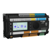
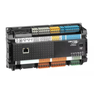
EAGLEHAWK CONTROLLER – INSTALLATION & COMMISSIONING INSTRUCTIONS
EN1Z-1005GE51 R0216 12
24 V~
24 V~0
LINE
L
N
EAGLEHAWK #1 EAGLEHAWK #2
CPU 2
NOISE-FREE EARTH GROUND
(ONLY ONE PER SYSTEM)
N, L
EARTH GROUND
USB 2.0
Device Interface
!
REVERSED
POLARITY!
SHORT-CIRCUITING!
PC 1 PC 2
2 21 1
24V~ 24V~24V~0 24V~0
Fig. 20. Incorrect polarity → SHORT-CIRCUITING!
Transformer Data
In Europe, if the EAGLEHAWK is powered by transformers,
then such transformers must be safety isolating transformers
conforming to IEC61558-2-6. In the U.S. and Canada, if the
EAGLEHAWK is powered by transformers, then such
transformers must be NEC Class-2 transformers.
Table 9. 1450 series transformers data
part #
1450 7287
primary side secondary side
-001 120 Vac 24 Vac, 50 VA
-002 120 Vac
2 x 24 Vac, 40 VA, 100 VA from
separate transformer
-003 120 Vac 24 Vac, 100 VA, 24 Vdc, 600 mA
-004 240/220 Vac 24 Vac, 50 VA
-005 240/220 Vac
2 x 24 Vac, 40 VA, 100 VA from
separate transformer
-006 240/220 Vac 24 Vac, 100 VA, 24 Vdc, 600 mA
Table 10. Overview of CRT Series AC/DC current
transformer primary side
max. AC
current
max. DC
current
CRT 2 230 Vac 2 A 500 mA
CRT 6 230 Vac 6 A 1300 mA
CRT 12 230 Vac 12 A 2500 mA
PRIMARY SIDE
EAGLEHAWK
1
2
24 VAC
230 VAC
120 VAC
24 V0
NOT
RECOMMENDED
Fig. 21. Connection of EAGLEHAWK controller
RIN-APU24
The RIN-APU24 Uninterruptable Power Supply can be
directly wired to an EAGLEHAWK controller.
See RIN-APU24 Uninterruptable Power Supply – Mounting
Instructions (EN0B-0382GE51) for a detailed wiring diagram.
Powering Panel Bus I/O Modules and Field Devices
The EAGLEHAWK, Panel Bus I/O modules, and field devices
can be powered by either separate transformers (see Fig. 22,
and Fig. 23) or by the same transformer.
NOTE: Use a min. distance of 10 cm between power cables
and 0…10 V / sensor cables in order to prevent
signal disturbances on the 0…10 V / sensor cables.
See also section “Cable Specifications” on page 18.
Powering Field Devices and Panel Bus I/O Module via Separate
Transformers
24 V actuator connected to, e.g., an analog output module
Field device located 100 … 400 m from the analog output
module
max. 400 m
CLIOP822A
73
74
1...8
GND
24 VAC
11...18
24 V0
230 VAC
24 VAC
F2
Y (0...10 Vdc)
24 V0
230 VAC
24 VAC
F1
Fig. 22. Power supply via a separate transformer
Powering Field Devices via Panel Bus I/O Module
24 V actuator connected to, e.g., an analog output module
Field device located max. 100 m from the analog output
module
Y (0...10 Vdc)
24 V0
230 VAC
24 VAC
max. 100 m
CLIOP822A
73
74
1...8
GND
24 VAC
11...18
F1
F2
Fig. 23. Power supply via Panel Bus I/O Module
Lightning Protection
Please contact your local Honeywell representative for
information on lightning protection.
 Loading...
