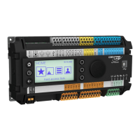
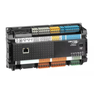
EAGLEHAWK CONTROLLER – INSTALLATION & COMMISSIONING INSTRUCTIONS
EN1Z-1005GE51 R0216 18
Cable Specifications
Panel Bus I/O Modules
When checking the length of the power supply cable, the
connection cables to all Panel Bus I/O Modules must be
taken into account.
Table 14. Power supply cable specifications
max. length
3 m (from transformer to final module)
cross section
min. 0.75 mm
2
(AWG 18)
EIA 485 Cable Specifications
The following cable specification is valid for all EIA 485 buses
(e.g., Panel Bus and BACnet MS/TP).
Table 15. EIA 485 cable specifications
max. length
1000 m
cable type
twisted pair, shielded (foil or braided
shields are acceptable)
characteristic
impedance
100…130 Ω
distributed
capacitance
between
conductors
Less than 100 pF per meter (30 pF per
foot)
distributed
capacitance
between
conductors and
shield
Less than 200 pF per meter (60 pF per
foot)
The following cables fulfill this requirement:
AWG 18;
shielded, twisted pair cable J-Y-(St)-Y 2 x 2 x 0,8;
CAT 5,6,7 cable (use only one single pair for one bus);
Belden 9842 or 9842NH.
Field Devices
Depending on the distance from the controller, field devices
can be supplied with power by the same transformer used for
the Panel Bus I/O Modules, or by a separate transformer,
using cables as specified in Table 16.
Table 16. Power / communication cable specifications
type of signal
cross-sectional area
100 m (Fig. 23)
single transformer
400 m (Fig. 22)
sep. transformers
24 VAC power 1.5 mm
2
(16 AWG)
not allowed for
> 100 m (300 ft)
0…10 V signals 0.081 – 2.08 mm
2
(28 – 14 AWG)
For wiring field devices, see section “Powering Panel Bus I/O
Modules and Field Devices” on page 12.
Routing Cables to Field Devices
Route low-voltage signal and output cables to field devices
separately from mains cables.
Table 17. Minimum distances to power mains cables
cable min. distance
shielded 10 mm (0.4 in.)
unshielded 100 mm (4 in.)
All low-voltage signal and output cables should be regarded
as communication circuits in accordance with VDE 0100 and
VDE 0800 (or NEC or other equivalent).
If the general guidelines for cable routing are observed, it
is not necessary to shield field device signal and power
supply cables.
If, for whatever reason, the routing guidelines cannot be
observed, the field device signal and power supply cables
must be shielded.
– Shielding of cables leading to field devices must be
grounded only at one end.
– Do not connect the shield to the EAGLEHAWK
controller.
 Loading...
