69-1285—28
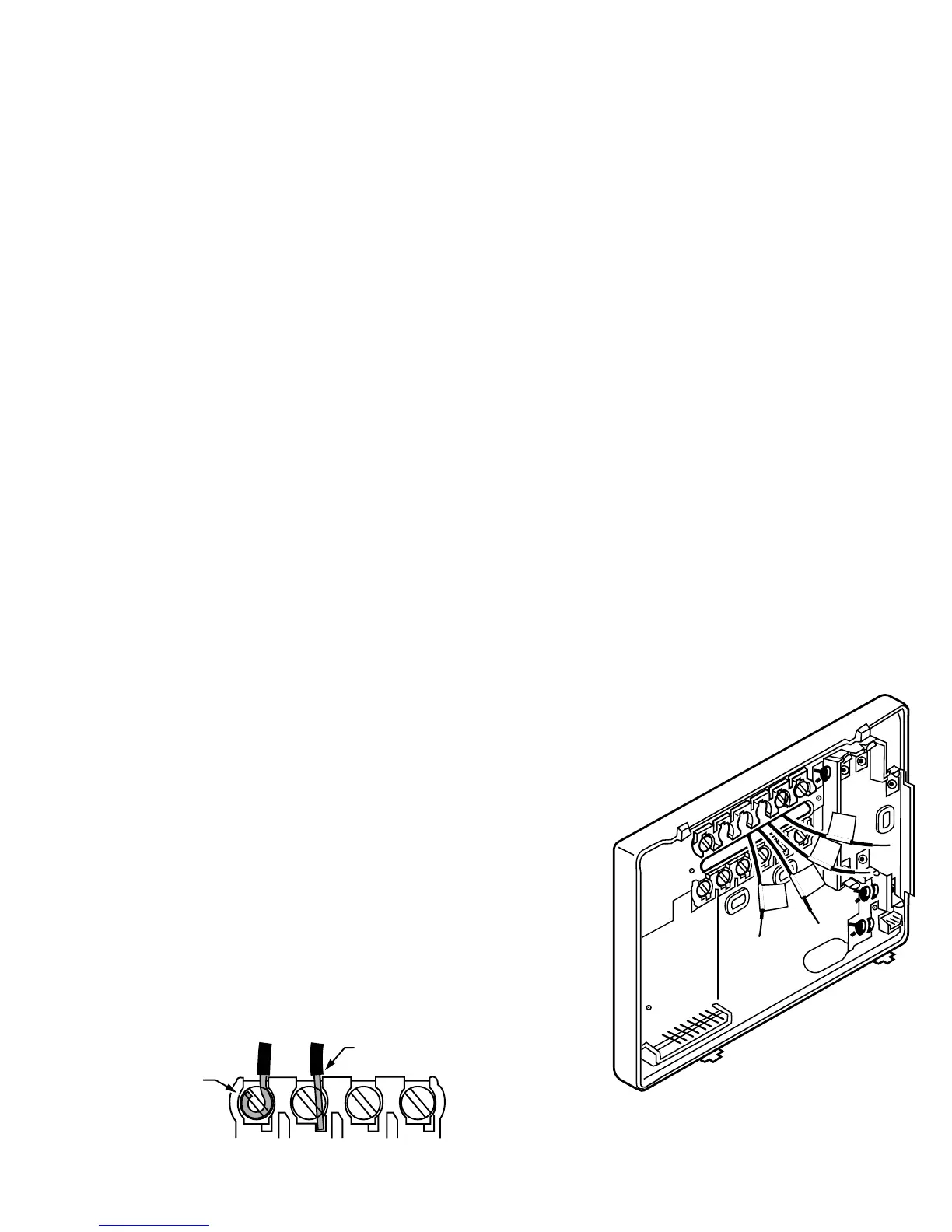
STEP 4. WIRE WALLPLATE TERMINALS
IMPORTANT
All wiring must comply with local codes and ordinances. If
unsure about household wiring procedures, call your local heat-
ing/air-conditioning contractor.
Refer to the labels
ou placed on the wires when
ou removed the old
thermostat (see illustration).
❑ Match the letter of
our old thermostat wire with the correspondin
our new thermostat. Refer to Table 2.
❑ Remove the factor
-installed jumper connectin
terminals R and RC if
wires are connected to both of those terminals.
❑ For wirin
rams, if needed, see pp 21-22.
❑ Loosen the terminal screws. Slip each wire beneath its matchin
terminal. Wraparound and strai
ht connections are both acceptable,
(see illustration). Ti
the hole in the wall with insulation to help prevent drafts from adversel
thermostat operation.
M16425
R
W
Y
G
M4826
FOR WRAPAROUND
INSERTION STRIP
7/16 IN. (11 MM).
FOR STRAIGHT INSERTION
STRIP 5/16 IN. (8 MM).
 Loading...