Honeywell GmbH 4 MU1H-1054GE23 R0215
GB
1. Safety Guidelines
1. Follow the installation instructions.
2. Use the appliance
• according to its intended use
• in good condition
• with due regard to safety and risk of danger.
3. Note that the appliance is exclusively for use in the appli-
cations detailed in these installation instructions. Any
other use will not be considered to comply with require-
ments and would invalidate the warranty.
4. Please take note that any assembly, commissioning,
servicing and adjustment work may only be carried out by
authorized persons.
5. Immediately rectify any malfunctions which may influence
safety.
2. Application
3. Technical data
4. Scope of delivery
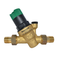
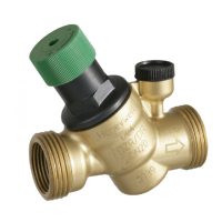
The pressure reducing valve comprises:
• Housing with pressure gauge connection G1/4"
• Spring bonnet with adjustment opening
• Green adjustment knob
• Adjustment spring
• Valve insert complete with diaphragm and valve seat
• Pressure gauge not included (see accessories)
5. Assembly
5.1. Installations Guidelines
It is necessary during installation to follow the installation
instructions, to comply with local requirements and to follow
the codes of good practice.
• Horizontal and vertical installation position possible
- In vertical installation position spring bonnet with adju-
stment knob facing upwards
• Install shutoff valves
• The installation location should be protected against frost
and be easily accessible
- Pressure gauge can be read off easily
- Simplified maintenance and cleaning
• For residential applications where maximum protection
against dirt is required, install a fine filter upstream of the
pressure reducing valve
• Provide a straight section of pipework of at least five times
the nominal valve size after the pressure reducing valve (in
accordance with EN806-2)
5.2. Assembly instructions
1. Thoroughly flush pipework
2. Install pressure reducing valve
• Note flow direction
• Install without tension or bending stresses
3. Set outlet pressure
6. Start-up
6.1. Setting outlet pressure
1. Close shutoff valve on inlet
2. Release pressure on outlet side (e.g. through water tap)
3. Fit manometer (standard version)
4. Close shutoff valve on outlet
5. Fit adjustment knob
6. Slacken tension in compression spring
• Turn adjustment handle counter clockwise (-) until it
does not move any more
7. Slowly open shutoff valve on inlet
8. Turn adjuster knob until the manometer shows the
desired value.
9. Slowly open shutoff valve on outlet
7. Maintenance
In accordance with EN 806-5, the following measures must
be taken:
7.1. Inspection
7.1.1. Pressure reducing valve
1. Close shutoff valve on outlet
2. Check outlet pressure using a pressure meter when there
is zero through-flow
• If the pressure is increasing slowly, the valve may be
dirty or defective. In this instance, carry out servicing
and cleaning
3. Slowly open shutoff valve on outlet
7.2. Maintenance
1. Close shutoff valve on inlet
2. Release pressure on outlet side (e.g. through water tap)
3. Close shutoff valve on outlet
4. Fit adjustment knob
5. Slacken tension in compression spring
• Turn adjustment handle counter clockwise (-) until it
does not move any more
6. Unscrew spring bonnet
7. Remove valve insert with a pair of pliers
Medium Water
Inlet pressure max. 16 bar
Outlet pressure 1.5-6 bar adjustable
Installation
position
Horizontal and vertical installation position
possible
In vertical installation position spring bonnet
with adjustment knob facing upwards
Operating
temperature
max. 40°C accord. to DIN EN 1567
max. 70°C (max. operating pressure 10 bar)
Minimum
pressure drop
1 bar
Connection size 3/8", 1/2", 3/4"
When using soldering connections, do not solder the
connections together with the pressure reducing valve!
High temperature will irreparably damage important
internal working components!
The green adjustment knob must stay plugged on to
prevent dirt from entering.
Set outlet pressure min. 1 bar under inlet pressure.
We recommend a planned maintenance contract with
an installation company
Interval: once a year
Frequency: every 1-3 years (depending on local opera-
ting conditions)
To be carried out by an installation company
 Loading...