In case of RSP(Input2), SET2.4=1.(It shows ANL2, ANH2.)
(2-3) Press the SET and shift key for 5 seconds and return to OPERATION.
4-3. How to Calibrate
(3-1) Preparation of sources
- DC Current source : DC 0~20mA or 4~20mA
- DC voltage source : DC 0~1V, 0~5V, 0~10V, 1~5V, 2~10V
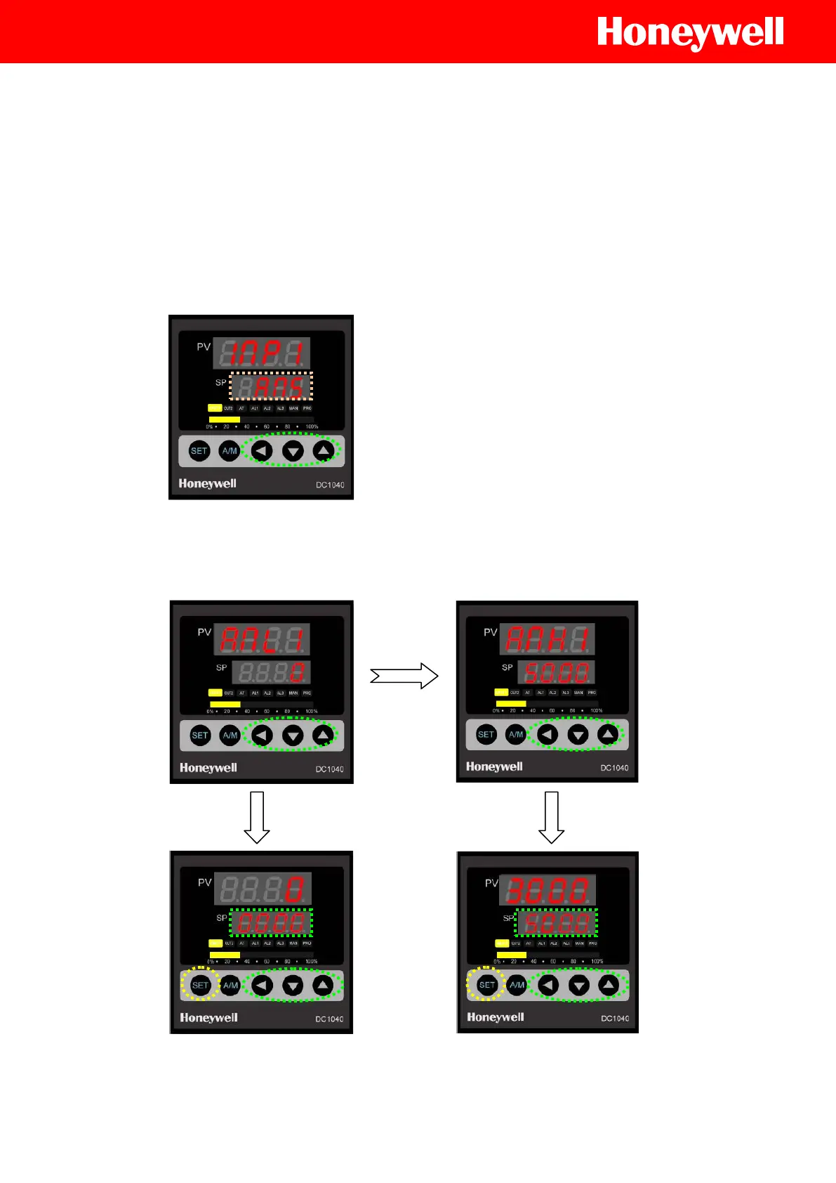
(3-2) Press the SET and shift key for 5 seconds, it will show ‘INP1’ of Configuration2.
Set INP1 to ‘AN5’ in case of DC 4~20mA.(Refer to INPUT CODE of ‘Linear input H/W setting’)
(3-3) Press the SET key just one time to show ANL1 parameter.
(3-4) Connect input source with INP1 terminals according to wiring diagram.
(3-5) Adjust the calibration values for Lower side(ANL1) and Upper side(ANH1).
In case of RSP(Input2), execute the calibration for each ANL2, ANH2.
(3-6) Refer to procedures as followings.
 Loading...


