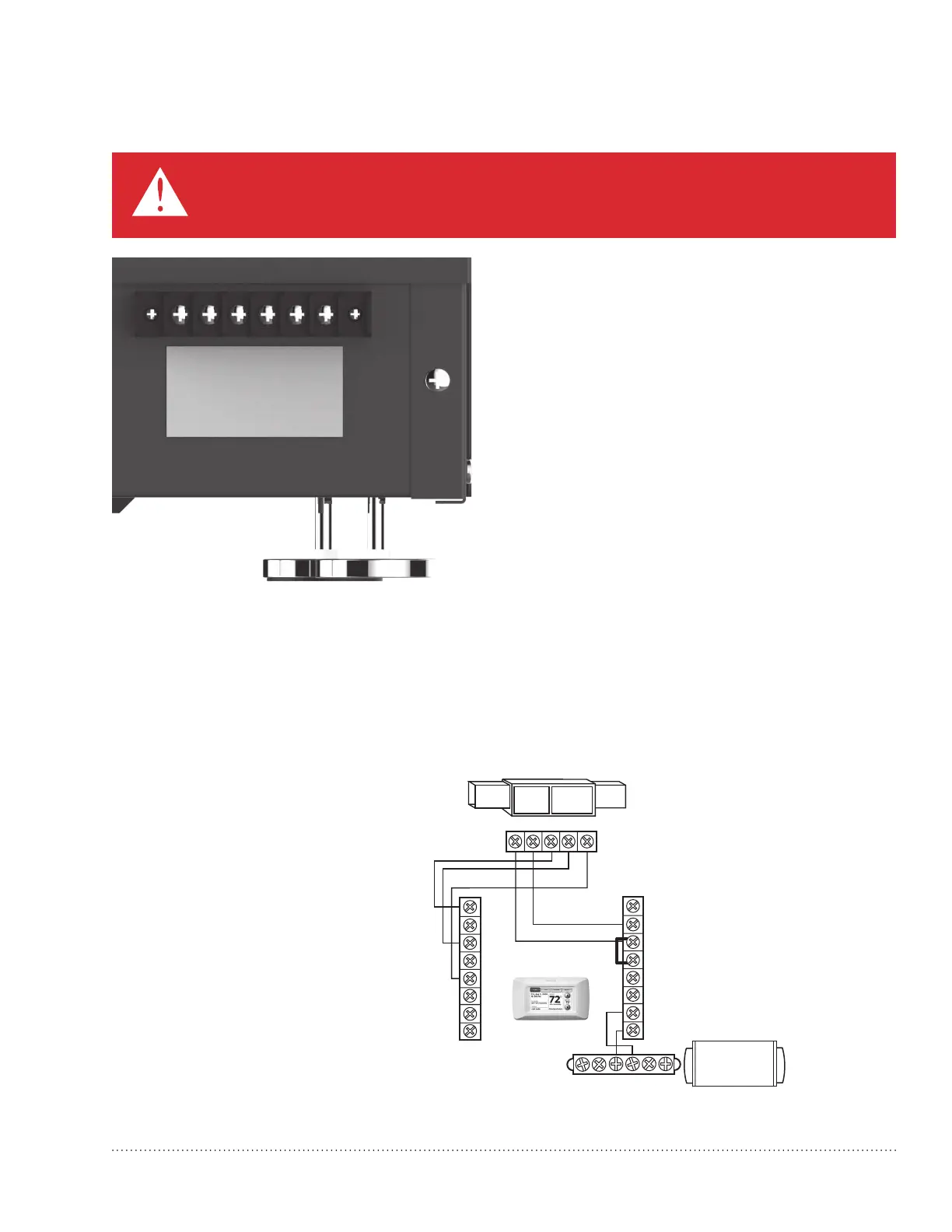
Terminal Description
NOTE: The outer screws on the terminal block
secure the block to the chassis. They are not used
for wiring.
A wiring terminal block is located on the side panel
of the dehumidifier unit.
The six terminals for the terminal block (reading
from left to right in the photo) are:
FLOAT: External low voltage float switch or
water sensor (two terminals). Use
normally closed switch.
DHUM: Compressor and fan operation for
dehumidification
R: DR90/DR120 24V output
FAN: Fan activation only for ventilation
C: DR90/DR120 24V output
External 24V devices can be powered from R and C
terminals (20VA max.).
Wiring
Wire the DR90/DR120A3000 according to the diagram that applies to your desired oper-
ation.
DR90/DR120A3000 Dehumidification System 33-00298EFS—01
8
Follow this diagram if using
the Prestige thermostat.
THERMOSTAT
GYWR C
M3685
C
Rc
R
H
H
DH
DH
W
W2
Y
Y2
G
K
THERMOSTAT MUST BE CONFIGURED TO DRIVE FURNACE FAN
DURING DEHUMIDIFICATION CALL.
DHUM
+
+
R
FAN
C
FLOAT
DEHUMIDIFIER
CAUTION: Low voltage hazard.
Can cause equipment damage.
Disconnect HVAC equipment before beginning installation.
 Loading...