3
Point Remote Gas Sensor User Manual
Wiring Diagram
Connecting the Main Sensor to the Remote
Wiring Diagram
Connecting the Main Sensor to the Remote
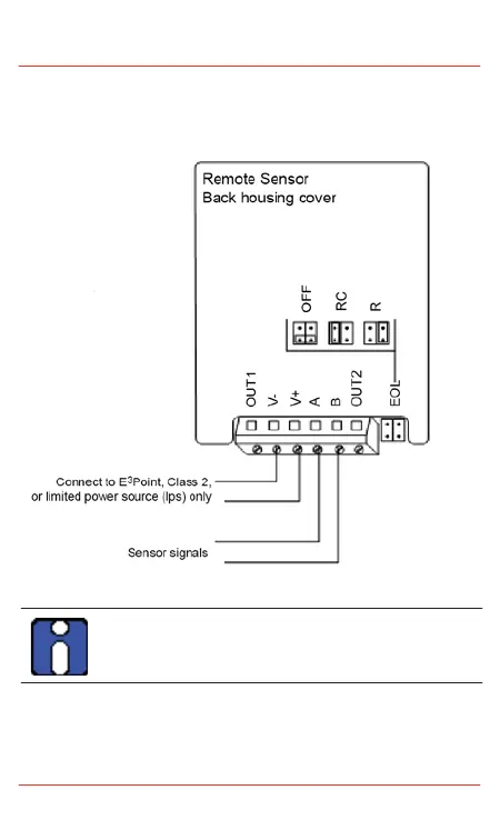
Figure 2. Connecting Main Sensor to Remote
The OUT1 and OUT2 connectors on the remote sensor’s
terminal are not used. DO NOT connect any wires to these
locations.
Wire: Signal wiring should be done with #20-24 AWG shielded
twisted pair cable Belden 9841 or similar. Network units should have
no more than 2,000 ft (600 m) of #22 AWG wire. Smaller gauge sizes
are limited by the same resistance limit. The LED on the faceplate
blinks to indicate communication with the main unit.
 Loading...