EC7830, RM7830A,EC7850A,RM7850A 7800 SERIES RELAY MODULES
3
66-1092—2
Wiring Subbase
CAUTION
Electrical Shock Hazard or Equipment Damage.
Can cause electrical shock or damage equipment.
Disconnect the power supply before beginning
installation.
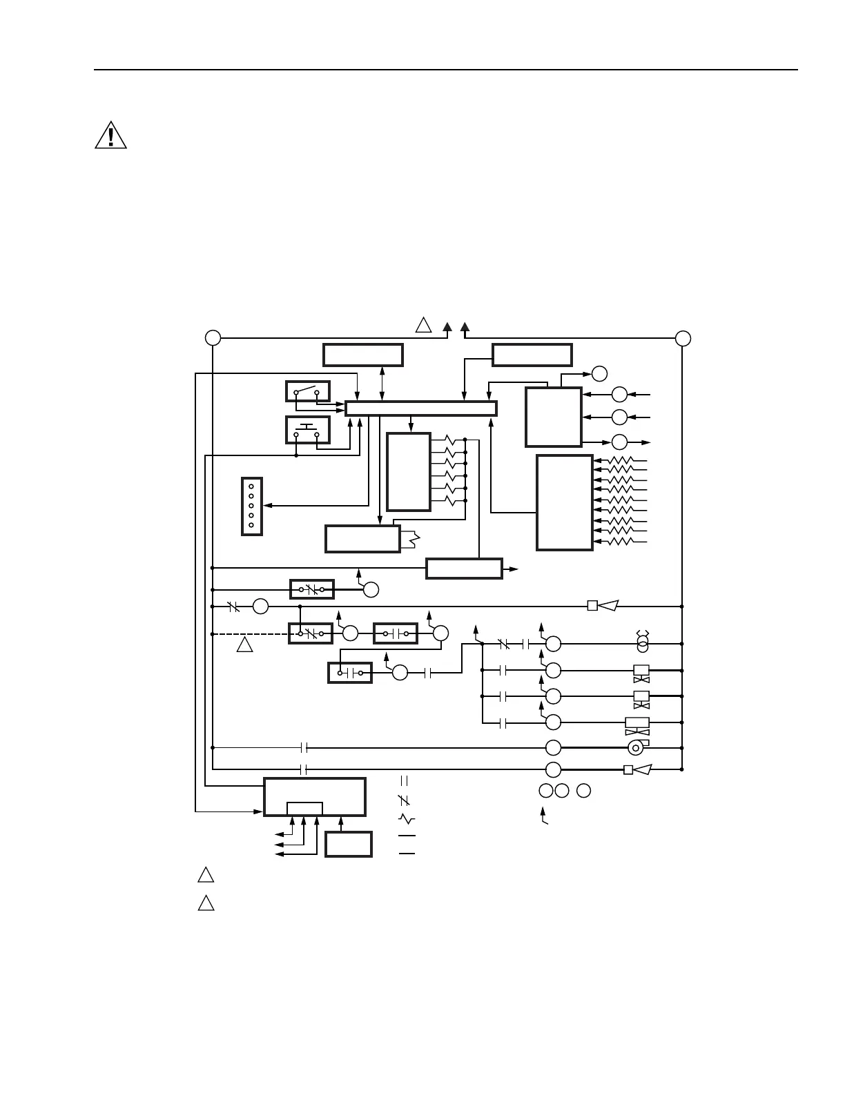
The internal block diagram of the EC/RM7830A is shown in
Fig. 1 and the internal block diagram of the EC/RM7850A is
shown in Fig. 2.
1. For subbase wiring and sequence charts, refer to Fig. 3
and 4.
2. For remote wiring of the KDM, refer to the
Specifications for the KDM (65-0090), Network
Interface Unit (63-2278), Data ControlBus Module™
(65-0091) or Extension Cable Assembly (65-0131).
3. Disconnect the power supply from the main disconnect
before beginning installation to prevent electrical shock
and equipment damage. More than one disconnect can
be required.
4. All wiring must comply with all applicable electrical
codes, ordinances and regulations. Wiring, where
required, must comply with NEC Class 1 (Line Voltage)
wiring.
5. For recommended wire size and type, see Table 1.
6. For recommended grounding practices, see Table 2.
Fig. 1. Internal block diagram of EC/RM7830A (see Fig. 3 for detailed wiring instructions).
L1
HOT
N
1
5
2
CONFIGURATION
JUMPERS
PLUG-IN PURGE
TIMER CARD
F
G
22
PLUG-IN
FLAME
AMPLIFIER
MICROCOMPUTER
RUN/TEST
SWITCH
RESET
PUSHBUTTON
FLAME SIGNAL
TEST
JACK
RELAY
DRIVE
CIRCUIT
1K
2K
3K
4K
5K
6K
7K
CONTROL
POWER
POWER SUPPLY
17
RELAY
STATUS
FEEDBACK
AND LINE
VOLTAGE
INPUTS
10
8
21
9
4
3
OPTIONAL KEYBOARD
DISPLAY MODULE
RS485
16
1K1
2K2 5K1
4K1
7K1
2K1
PV1
PV2
MV
3K1
6K1
7
ES2
3K2
20 6
FAN
AL
IGN
AL
DDL
REMOTE
RESET
INDICATES FEEDBACK SENSING
OF RELAY CONTACT STATUS
AND LINE VOLTAGE INPUTS
RELAY CONTACT OPEN
INTERNAL WIRING
FIELD WIRING
RELAY COIL
RELAY CONTACT CLOSED
DDL
COMMUNICATIONS
1
2
3
5
F G ... 22
USER TERMINALS
1
2
2
120 VAC, 50/60 Hz POWER SUPPLY, RM7830A; 220-240 VAC, 50/60 Hz POWER SUPPLY, EC7830A.
PROVIDE DISCONNECT MEANS AND OVERLOAD PROTECTION AS REQUIRED.
TO CONNECT L1 DIRECTLY TO LOS, AT LEAST ONE CONTROLLED SHUTDOWN MUST BE PROVIDED EVERY 24 HOURS.
M15183B
STATUS
LEDS
RTLOS
LD2
SHUTTER
SAFETY RELAY
CIRCUIT
 Loading...