Installation Guide and Operating Manual // Model FS20X™ Series
Honeywell 17
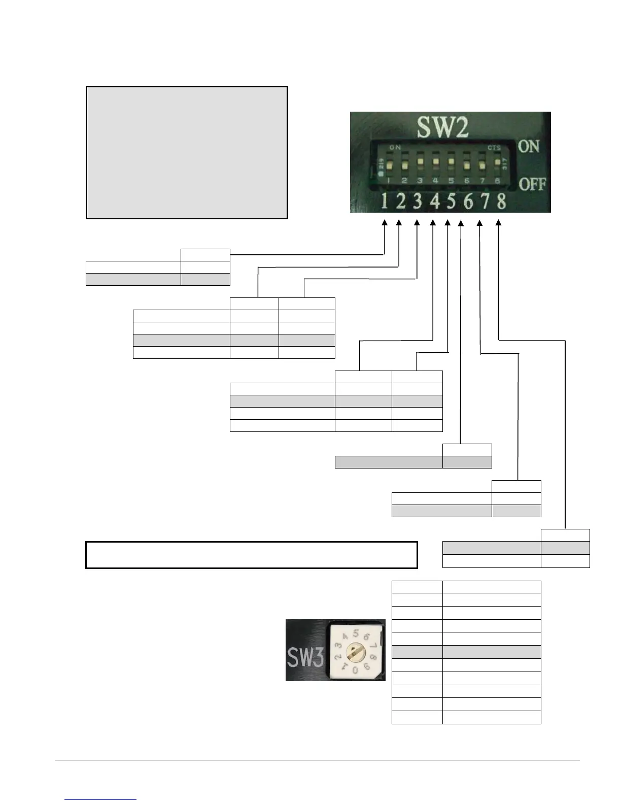
Configuring the Detector (continued)
CAUTION - WARNING
When the switches SW1,
SW2, or SW3 are changed,
the Detector’s input power
must be cycled OFF, then
ON, in order for the
change(s) to be accepted.
Eight (8) position DIP Switch (SW2) - Figure 3-2
Use the following table to configure the Detector:
Alarm Relay SW2-1
Latching ON
Non-Latching OFF
Sensitivity Levels SW2-2 SW2-3
Very High (4) ON ON
High (3) ON OFF
Medium (2) OFF ON
Low (1) OFF OFF
Auxiliary Relay SW2-4 SW2-5
No Verify Time ON ON
5 Sec Verify Time ON ON
10 Sec Verify Time OFF ON
20 Sec Verify Time OFF OFF
SW2-6
Factory Use Only
OFF
Alarm Relay SW2-7
Factory default settings are shown with a gray background. Energized ON
De-Energized OFF
Fault Relay SW2-8
*If the Fault Relay to set to “De-Energizied”, the Detector will not report
any faults due to loss of input power to the Detector.
Energized ON
De-Energized* OFF
Analog and digital outputs are available
in addition to relay outputs. Select from
two (2) analog outputs or two (2) digital
outputs using a ten (10) position Rotary
Switch (SW3). FireBus
II is the factory
default setting. Use Table on the right
and Figure 3-3 to configure SW3.
Position
Output Selection
0 4-20 mA Sink
1 4-20 mA Source
2 RS-485 ModBus
3
Factory Use Only
4
RS-485 FireBusII
5 Factory Use Only
6 Factory Use Only
7 Factory Use Only
Figure 3-3 SW3
8 Factory Use Only
Ten (10) Position Rotary Switch
9 Factory Use Only
Note:
The Low Sensitivity range is not approved as compliant with the requirements of EN 54-10:2002.

 Loading...


