Installation Guide and Operating Manual // Model FS20X™ Series
Honeywell 7
SECTION 2: INSTALLATION
2.1 Mounting Instructions
Consider the following guidelines when selecting Detector location:
1. As with all flame and fire Detectors, avoid areas that contain radiant energy sources (such as radiant
heaters, high intensity lamps, flare-stacks, etc.) in close proximity to the Detector’s field of view.
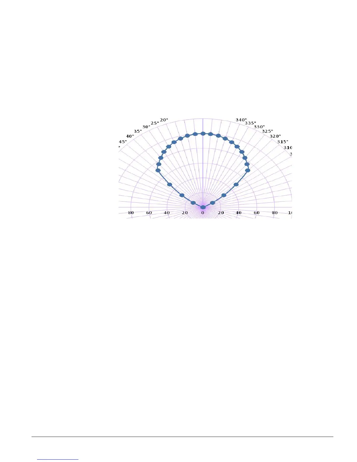
2. The installation shall take into account that the FS20X orientation should be with the base horizontal
(see Figure 2-1) as the view angle in this direction is 90°. The vertical angle is 80°.
Horizontal Field of View
Figure 2-1
FS20X Graphical View
3. Detectors should not be mounted so that they look up or face the horizon (especially outdoors). Use
a minimum thirty degrees (30°) downward angle with the SM4 swivel mount (see Figure 2-2).
4. Make sure the Detector has a clear, unobstructed view of the threat area. Physical obstructions
between a fire and the Detector may cause the fire to be undetected.
5. The Model SM4 is a 316 Stainless Steel Swivel Mount designed for the FSC Detector housing. The
adapter plate, with the two (2) screw holes (facing away), is attached to the base of the Detector (see
Figure 2-2). The mounting plate, with the four (4) screw holes (facing towards), is used for mounting
the SM4 to a solid surface. Each adjustment increment along an axis is calibrated to 10°. For single
axis adjustments, the center section need not be installed.
6. Avoid mounting the Detectors in areas where temperatures exceeds the specified operating
temperature range (see Sections 1.2.3 & 1.2.5).
7. Detector Conduit Entries
a) If only one conduit entry is used, correctly install and seal the conduit plug on the unused entry,
¾ in. NPT or 25mm (see Figure 2-3).
b) Install an approved conduit trap or drain, if required to meet hazardous area classifications per
NFPA 70: National Electrical Code, latest revision.
Note: The maximum specified FOV is the angle at which the detector can detect a flame at 50% of
the maximum specified range. To comply with the directional dependence requirements for EN 54-
10:2002, an angle of ±40° (80°) from 0° (where 0° is the orientation of the detector in the same axes
as the flame source) should not be exceeded, based on lab testing at a distance of approximately
5.3 ft (1.6 m).

 Loading...


