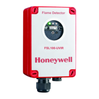
Installation Guide and Operating Manual // Model FS20X™ Series
Honeywell 3
1.2 Detector Technical Specifications
1.2.1 Mechanical Specifications
Enclosure Material: Copper Free Aluminum (red)
316 Stainless Steel
Physical Dimensions: Assembly 4.35 in. (
110.49 mm) Height X 4.81 in. (122.24 mm) Diameter
Mounting Holes ¼ in. (
6.35 mm) Diameter, 5.50 in. (139.70 mm) Center to Center
Conduit Entries Two (2) ¾ in. NPT or Two (2) 25 mm
Weight: Aluminum 3 lbs. 11 oz. (
1.7 kg) approximately
Stainless Steel 7 lbs. 7 oz. (
3.4 kg) approximately
Enclosure Rating: IP66 / NEMA 4 / NEMA 4X
Vibration: Meets or exceeds Mil Spec 810C,
Method 514.2, Curve AW
1.2.2 Electrical Specifications
Input Voltage Range: 18 VDC to 32 VDC
Normal Operation Current: 85 mA (
nominal) 175 mA (nominal with heaterP
1
P
)
Maximum Fire Alarm Current: 135 mA (
maximum) 220 mA (maximum with heaterP
1
P
)
Relay Contact Rating: 1 Amp @ 24 VDC resistive
Analog Current Output: 0.0 to 20.0 mA (
Non-Isolated Source or Sink, User Selectable)
(
400 Ohms Max Load [loop resistance]) 0.0 mA (<0.6 mA) = Fault
2.0 mA (
±0.6 mA) = Dirty Window Lens
4.0 mA (
±0.6 mA) = Normal, Safe (no Fault, no Fire)
8.0 mA (
±0.6 mA) = Background IR
12.0 mA (
±0.6 mA) = Background UV
16.0 mA (
±0.6 mA) = Fire Alarm
20.0 mA (
±0.6 mA) = Verified Fire Alarm
Screw Terminal Wire Sizes: 12 AWG to 22 AWG (
2.50 mm to 0.762 mm)
Use stranded conductors (
UnotU solid core)
1.2.3 Environmental Specifications
Operating Temperature Standard: -40° F to +185° F (-40° C to +85° C)
Operating Humidity Range: 0 to 95% RH,
100% RH condensing for short periods of time
Storage Temperature: -67° F to +221° F (-55° C to +105° C)
1.2.4 Performance Specifications
P
2
P
Field of View: FS20X detectors have a cone of view of 90° horizontal and
80° vertical with the highest sensitivity on the central axis
Sensitivity One (1) sq. ft. heptane fire at 200 feet (
± 45° from axis)
Speed of Response: Typically, 2 to 5 seconds
High Speed Response: Less than 0.5 seconds to “fireball” type fires
Spectral Sensitivity ~0.185 to 0.26 microns and 0.4 microns to 3.5 microns
1.2.5 Hazardous Area Classifications (See Section 4.7.3 on Pages 32)
Class
I, Division 1, Groups A, B, C & D
Class
II, Division 1 Groups E, F & G Class I, Zone 1, AEx d/ Ex d IIC
Class
III Ex db IIC, Ex tb IIIC
T4: Ta = -40°C to +110°C T4: Ta = -40°C to +110°C
T5: Ta = -40°C to +75°C T5: Ta = -40°C to +75°C
T6: Ta = -40°C to +60°C T6: Ta = -40°C to +60°C
1
P
Heater circuit turns ON only when temperature drops below zero degrees Fahrenheit (-17° C)P
2
The supply connection wiring shall be rated at least 10°C above the rated service temperature (120°C for T4 applications and 85°C for
T5 applications)
 Loading...


