Installation Guide and Operating Manual // Model FS20X™ Series
Honeywell 10
7. Slide the Detector Module “puck” out of the
enclosure base (see Figure 2-9).
Figure 2-9
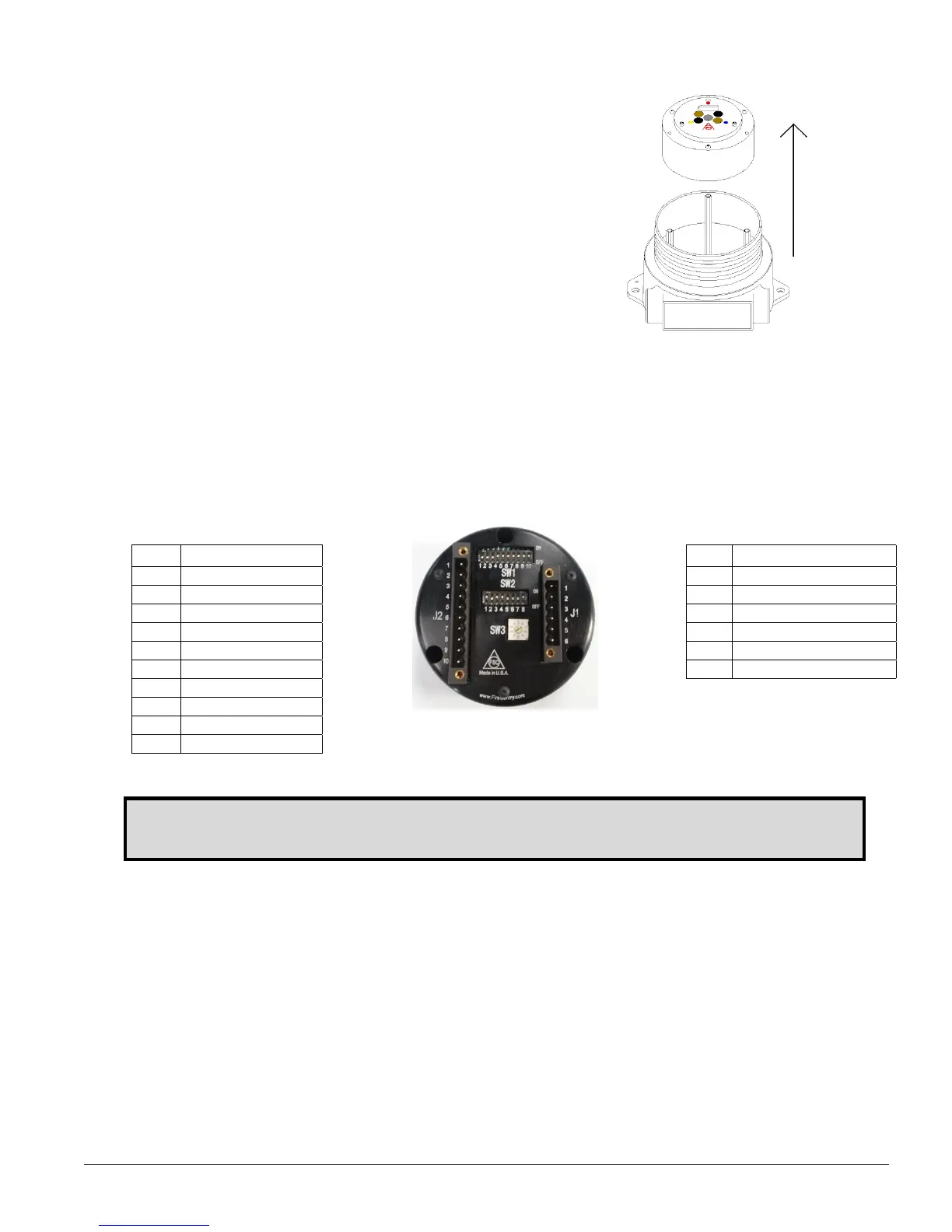
2.3 Detector Connections
The Detector Module puck has a six (6) pin and a ten (10) pin keyed removable connector with screw terminal
female plugs that connect to the two (2) respective male connectors with analog, digital, and relay interfaces
(see Figure 2-10):
For relay configurations, use the ten (10) pin plug (J2) and its connector.
For digital and analog configurations, use the six (6) pin plug (J1) and its connector.
J2 Connector
Figure 2-10
Detector Module “puck” (rear view)
J1 Connector
Pin Connection Pin Connection
1 Auxiliary NC 1 DC Return
2 Auxiliary NO 2 RS-485-A
3 Auxiliary COM 3 RS-485-B
4 Alarm NC 4 +24 VDC
5 Alarm NO 5 4-20mA Source
6 Alarm COM 6 4-20mA Sink
7 Fault NO
8 Fault COM
9 +24 VDC
10 DC Return
Contacts shown with
no power applied
Note: Do not attempt to open the Detector Module “puck” as this voids all warranties.

 Loading...


