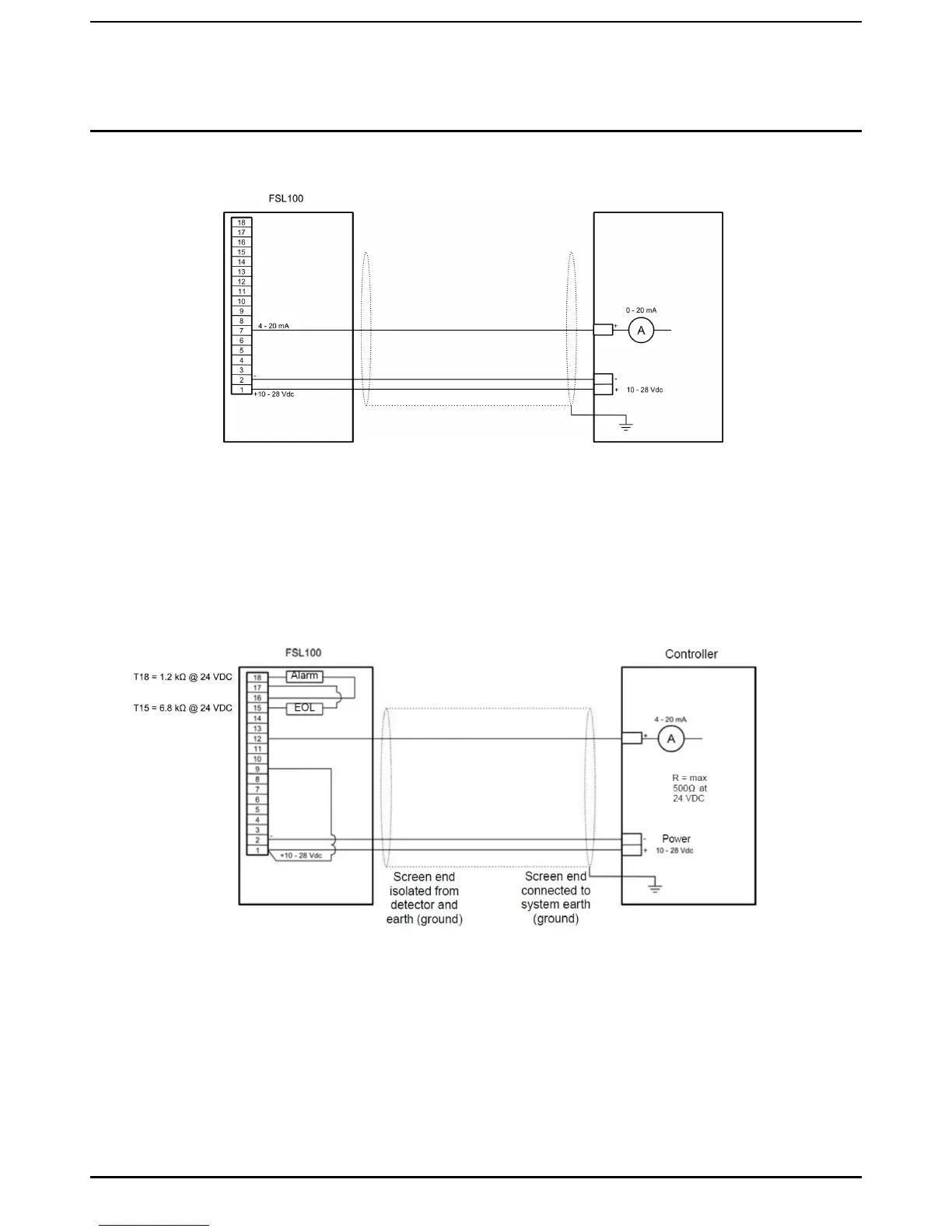
5.8 Wiring to a PLC
PLC
R = max
500Ω at
24 VDC
Screen end
isolated from
detector and
earth (ground)
Screen end
connected to
system earth
(ground)
Figure 12. Wiring to a PLC
Notes
1. 0-20 mA sinking analogue output, non-isolated.
5.9 Wiring to a 4-20 mA Non-Isolated (Sourcing) Current Output
The FLS100 detectors can be wired to a 4-20 mA non-Isolated (Sourcing) Output by using the controller’s alarm and fault
relays, as shown below.
Figure 13. Wiring to a 0-20 mA Non-Isolated (Sourcing) Current Output
The 4-20 mA sourcing output has the following values:
≥4 mA = Normal operation
≥20 mA = Alarm
0 mA = Fault (the 0 mA current will change to ≥20 mA (alarm) if flames are detected while the source is in fault)
Note:
This configuration has 2 wires connected to T1, but you should check if this is forbidden by your local regulations.

 Loading...


