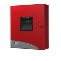
Specifications Product Description
• Low AC voltage sense
• Alarm Verification
• NACs Programmable for:
Silence Inhibit
Auto-Silence
Strobe Synchronization (System Sensor, Wheelock, Gentex, Faraday, Amseco)
Selective Silence (horn-strobe mute)
Temporal or Steady Signal
Silenceable or Nonsilenceable
• Automatic battery charger with charger supervision
• Silent or audible walktest capabilities
• Optional PK-CD (contains PS-Tools utility) for local or remote Upload/Download of program and data
• Optional CAC-5X Class A Converter Module for NACs and IDCs
• Optional 4XTMF Transmitter Module
• Optional ANN-SEC card for a secondary ANN-BUS
1.2 Specifications
AC Power
GF505 & GF510 (FLPS-7 Power Supply): 120 VAC, 60 HZ, 3.90 amps
Wire size: minimum #14 AWG (2.0 mm
2
) with 600V insulation
Supervised, nonpower-limited
Battery (sealed lead acid only) - J12
Maximum Charging Circuit - Normal Flat Charge: 27.6 VDC @ 1.4 amp
Supervised, nonpower-limited
Maximum Charger Capacity: 26 Amp Hour battery for GF505 & GF510 [two 18 Amp Hour batteries can be housed in FACP cabinet.
Larger batteries require a separate battery box such as the BB-55F and the FCI-CHG-120 Battery Charger.]
Minimum Battery Size: 7 Amp Hour
Initiating Device Circuits - TB4 (and TB6 on GF510 only)
Alarm Zones 1 - 5 on TB 4 (GF505)
Alarm Zones 6 - 10 on TB6 (GF510 only)
Supervised and power-limited circuitry
Operation: All zones Style B (Class B)
Normal Operating Voltage: Nominal 20 VDC
Alarm Current: 15 mA minimum
Short Circuit Current: 40 mA max.
Maximum Loop Resistance: 100 ohms (700 ohms per zone for linear heat detection - See Section 2.3, “Input Circuits” for more informa-
tion.)
End-of-Line Resistor: 4.7KΩ, 1/2 watt (Part #71252)
Standby Current: 2 mA
Refer to the Gamewell-FCI Device Compatibility Document for listed compatible devices
Notification Appliance Circuit(s) - TB5 and TB7
Four NACs
Operation: Style Y (Class B)
Special Application power
Supervised and power-limited circuitry
Normal Operating Voltage: Nominal 24 VDC
Maximum Signaling Current: 7.0 amps for GF505 & GF510 (3.0 amps special application, 300 mA regulated maximum per NAC)
End-of-Line Resistor: 4.7KΩ, 1/2 watt (Part #71252)
Refer to the Gamewell-FCI Device Compatibility Document for compatible listed devices
Form-C Relays - Programmable - TB8
Relay 1 (factory default programmed as Alarm Relay)
Relay 2 (factory default programmed as fail-safe Trouble Relay)
Relay 3 (factory default programmed as Supervisory Relay)
Relay Contact Ratings: 2 amps @ 30 VDC (resistive), 0.5 amps @ 30 VAC (resistive)
NOTE: For wiring specifications, refer to“Wire Requirements” on page 115.
GF505 & GF510 Manual — P/N 53164:B5 6/12/2018
13

 Loading...


