Input Circuits Installation
Initiating Device Circuits can be converted to Style D (Class A) by installing the optional Class A Converter module. Refer to “CAC-5X
Class A Converter Module” on page 29.
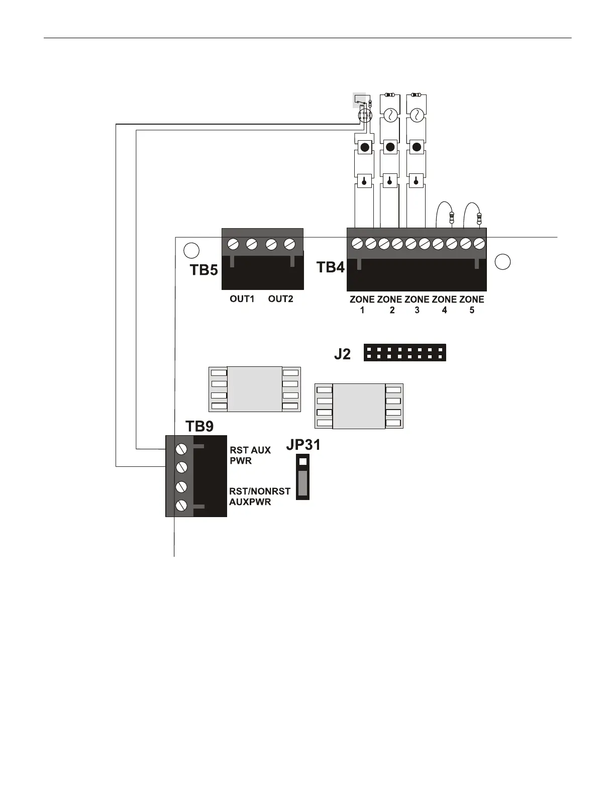
Figure 2.5 IDC Connections
Class B Initiating Device Circuits (supervised and power-limited) 4.7 KΩ, ½ watt resistor P/N:71252
UL listed compatible
2-wire smoke detectors
manual pull stations
heat detectors
Dummy load all unused
circuits - 4.7 KΩ, ½ watt
resistor (P/N: 71245)
ms-10UDidc.wmf
UL listed Power Supervision Relay
(refer to Device Compatibility Document for list of compatible relays)
Resettable 24 VDC
4-wire smoke
detector powe
r
(500 mA maximum)
UL listed compatible 4-wire smoke detector
GF505 & GF510 Manual — P/N 53164:B5 6/12/2018
23

 Loading...


