33-00288EF—03 2
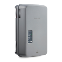
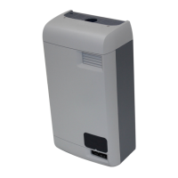
HM750A1000 Advanced Electrode Steam Humidifier
Mounting to the Supply Duct
The HM750 can also be mounted directly onto the supply duct. In this case, the
steam hose and the hose adapter must be removed as follows:
1.
Remove the humidifier cover
, loosen the hose clamp nearest to the cylinder
steam outlet and remove the cylinder.
2.
Remove the 3-inch steam hose.
3.
Remove the hose adapter by pres
sing on the release tab towards the back of
the humidifier and sliding the hose adapter downwards.
4.
Remove the steam distributor noz
zle from the steam hose.
5.
Inser
t the duct-mount baffle into the nozzle and then install the nozzle
directly onto the humidifier at the spot where the hose adapter was removed.
6.
Use the included 3
in. black hose to connect the cylinder to the steam
distributor and secure with hose clamps at both ends.
The HM750 is now ready for duct-mount (see Fig. 3). Using the mounting
template and thread-cutting screws (included), install the humidifier directly to
the air supply duct as follows:
1.
Drill 13/4” hole in duct to inser
t the steam distributor nozzle.
2.
Inser
t the top screw until 1/4 in. (6 mm) is exposed. Hang the humidifier via
its keyhole on the screw head (see Fig. 4).
NOTE
The donut-shaped foam gasket must be installed between the humidifier
and the duct.
3.
Af
ter making sure the humidifier is level, secure it to the duct using two
screws at the duct-mount locations (Fig. 4), and then replace the cover.
WATER CONNECTIONS
Requirements
• Use potable water;
• Pressure: 15100 PSIG;
•
DO NOT use reverse osmosis or de-ionized water
.
•
Conductivit
y: 1251200 microsiemens/cm
• Temperature: 39 to 86 °F (4 to 30 °C).
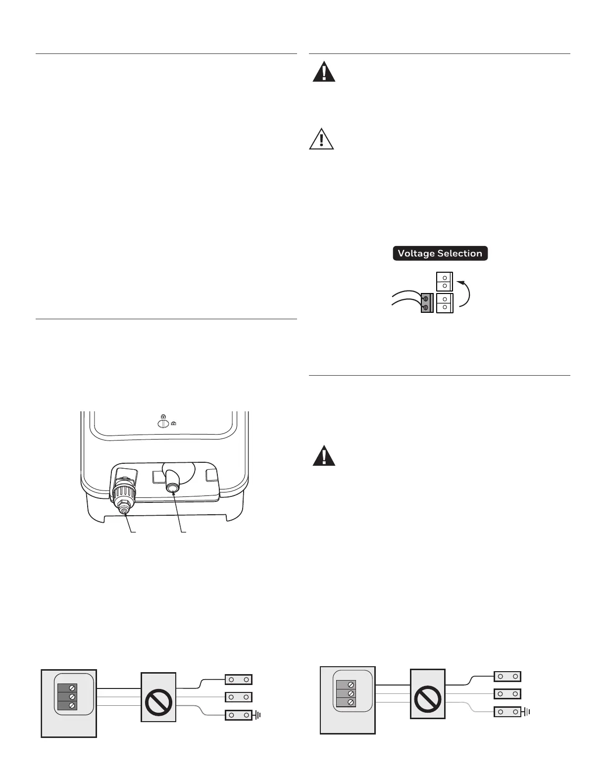
Connecting the Water Line
SUPPLY
CONNECTION
DRAIN
CONNECTION
Fig. 5. Water supply and drain connections.
Connect the water supply to the water inlet connection using copper pipe or
supplied LDPE pipe. This is done by pushing the water pipe into the “push-to-
connect” connection.
Connecting the Drain Line
Connect the drain hose (supplied) to the drain connection (Fig. 5). The
humidifier contains an internal air gap, so the drain hose can be connected
directly to the red drain spigot using a gear clamp (included). A condensate
pump can be used as the drain water is always tempered.
MAIN SUPPLY
L1
L2/N
GND
(OPTIONAL)
OFF ON
HOT
NEUTRAL
Fig. 7. 120 VAC (1 Phase) Primary power connection.
ELECTRICAL CONNECTIONS
WARNING
Wiring must be performed by a licensed electrician.
Do not remove the front cover when the humidifier is
powered.
CAUTION
Equipment Damage Hazard
Failure to wire the humidifier as per wiring instructions may cause
permanent damage to the product and will void the warranty.
Voltage Selection
To select the correct voltage (120 VAC or 240 VAC), ensure that the jumper is
properly placed between the appropriate terminals of the humidifier control
board. The HM750 is factory-configured for 240 VAC. If the humidifier will run
on a 120 VAC circuit, move the jumper to the 120 VAC terminals as seen in Fig. 6.
240VAC
120VAC
Fig. 6. Voltage selection jumper on humidifier control board.
Connecting Power
Requirements
• 12 AWG or 14 AWG wire
• Dedicated 15 amp, 120/240-volt circuit (a GFCI circuit is recommended)
•
Disconnect switch (optional
. The use of a disconnect switch between the
humidifier and the circuit breaker is recommended and will be useful for
future servicing.).
WARNING
To comply with UL product listing, the HM750 must be
hardwired to a dedicated 15 amp circuit breaker. All wiring
must be done per governing electrical codes. Failure to do
so will void the product warranty.
The use of electric cord plugs can cause overheating and result in risk
of damage to property and/or personal injury.
Wiring Procedure
1. Install a disconnect switch between the humidifier and the circuit breaker as
shown in Fig. 7 and Fig. 8 (optional).
2. Route the power supply wire through the strain relief located at the top of the
red electrical box.
3. Connect the power wires to MAIN SUPPLY terminals (L1, L2/N, and GND)
on the humidifier control board.
MAIN SUPPLY
L1
L2/N
GND
(OPTIONAL)
OFF ON
HOT
HOT
Fig. 8. 240 VAC (1 Phase) Primary power connection.
 Loading...