3 33-00288EF—03
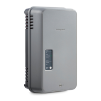
HM750A1000 Advanced Electrode Steam Humidifier
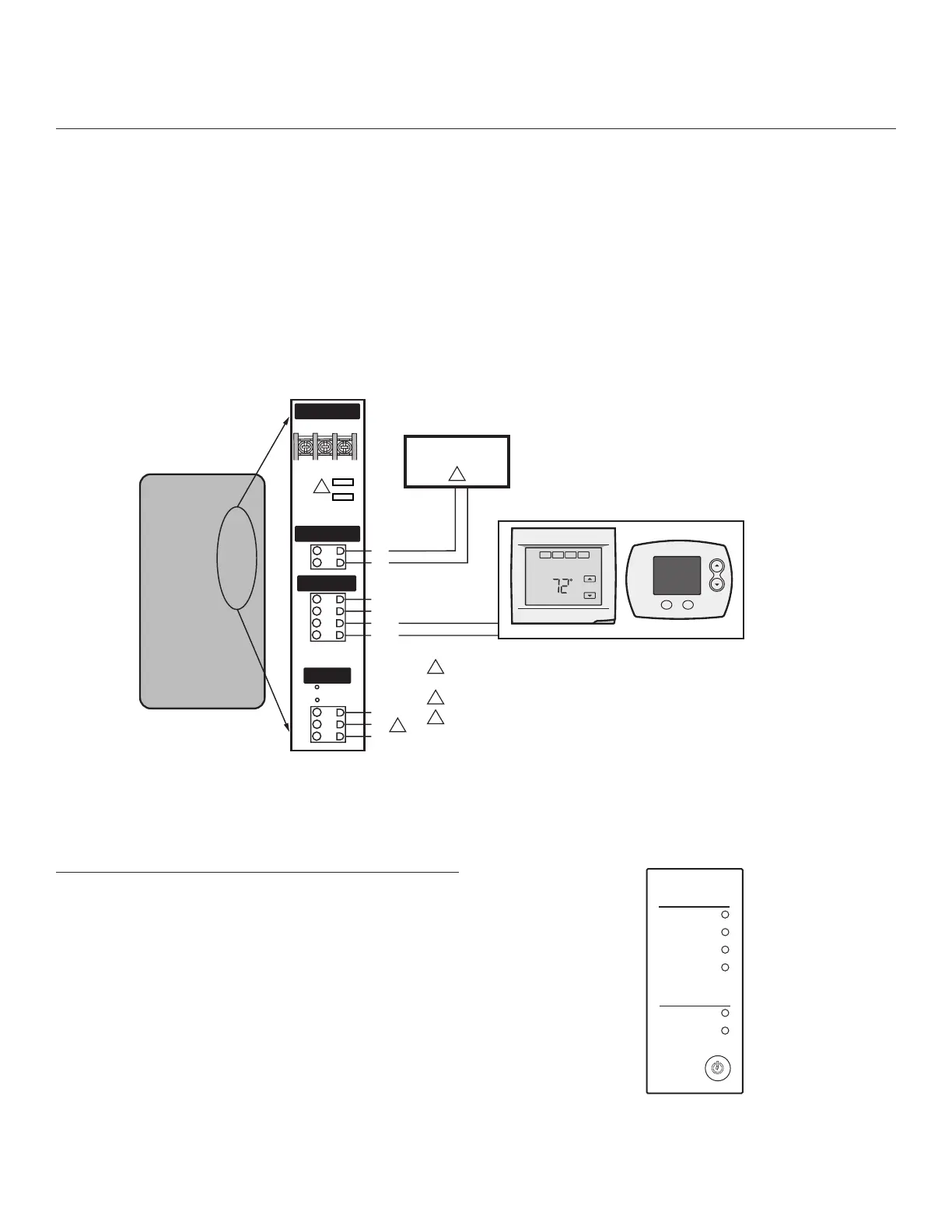
ELECTRICAL
Connecting Low-voltage Controls
Requirements
• 18 AWG solid wire or greater.
•
Low voltage wiring must be routed through the hole that is to the lef
t of the
high voltage strain relief.
•
K
eep control wires as short as possible.
Wiring Procedure
The humidifier can be connected to the following three devices (Fig. 9):
1. Humidistat or thermostat
2.
Air P
roving device (recommended)
3.
External fan (optional)
Humidistat or Thermostat Connection
Connect a humidistat or thermostat to the
HUM terminals of the humidifier.
The humidifier provides a 24VAC source to power the humidistat or
thermostat if needed (5 VA max.).
Air Proving Device
Honeywell recommends the use of an Air Proving device such as Honeywell
Differential Pressure Switch (50027910001) to ensure steam is distributed
only when there is air circulation. Connect the air proving device to the AP
terminals. If you do not install an air proving device, place a jumper between
the AP terminals.
Fan Interlock
Connect an external fan (optional) to the EXTERNAL terminals. The fan will
turn on whenever there is a call for humidity.
AIR PROVING
(OR JUMPER)
THERMOSTAT OR HUMIDISTAT
24VAC
COM
HUM
HUM
AIR PROVING JUMPER COMES PRE-INSTALLED.
REMOVE JUMPER IF AIR PROVING IS UTILIZED.
AP
AP
GT
RF
GF
Main Supply
Air Proving
Humidistat
External
L1
L2/N GND
2
3
1
1
WIRING FOR FAN INTERLOCK EQUIPMENT (OPTIONAL)
2
WHEN SHIPPED, THE INTERNAL GROUND IS CONNECTED TO THE J13 TERMINAL
FOR COMPATIBILITY WITH MOST GFCI AND NON-GFCI CONNECTIONS.
IF THERE ARE ISSUES WITH GFCI, MOVE THE GREEN WIRE FROM J13 TO J14.
3
J14J13
Fig. 9. Control wiring overview.
LED INDICATORS
Idle The humidifier is on but there is no call to humidify.
Filling - The humidifier is on and has a call to humidify; the cylinder is
currently filling up.
Humidifying - Humidifier is on and has a call to humidify. The cylinder should
be producing steam. There may be a delay before steam is visible.
Draining - The cylinder is being drained either from extended idle time to
prevent stagnant water, or the drain has been manually activated. When a
manual drain is initiated, there may be a brief delay while the hot water is
tempered.
Cylinder - When blinking, the cylinder has a limited time of service remaining.
When solid, the cylinder life has expired. Replace the cylinder.
Fault - When blinking, there is a fault present. Review the fault code label
behind the humidifier cover for more information, or contact your local service
professional.
Power - If the humidifier is off (no LEDs illuminated), pressing the Power
button for one second turns the unit on. If the humidifier is on, pressing the
power button for one second initiates the power down function (cylinder
drains, then unit shuts off). Pressing and holding the power button for 5
seconds resets any fault conditions.
HM750
Status
Idle
Filling
Humidifying
Draining
Service
Cylinder
Fault
Power
Drain
Fault Codes In Front Cover
Fig. 10. LED panel
 Loading...