12 HPF24S Series Power Supplies — P/N 52751:E1 4/14/2011
System Overview Specifications
– 500 mA maximum with external 18.0 Amp Hour batteries
1 2 3 4 5 6 7 8
ON
TB1
J2
TRANSFORMER 2
TRANSFORMER 1
J1
F1
JP4
- +
EARTH NEUT HOT
OUT4
- NAC4 +
OUT3
- NAC3 +
OUT2
- NAC2 +
OUT1
- NAC1 +
3 2 1
10
9
8
7
6
5
4
3
2
1
AUX -
IN2-
IN2+
OUT1-
OUT1+
IN1-
IN1+
SYNC IN -
SYNC IN +
AUX +
NO NC
AUX TBL
COM
BATTERY
AC
BATT
AC/
CHGR
GND
FLT
NAC
TRBL
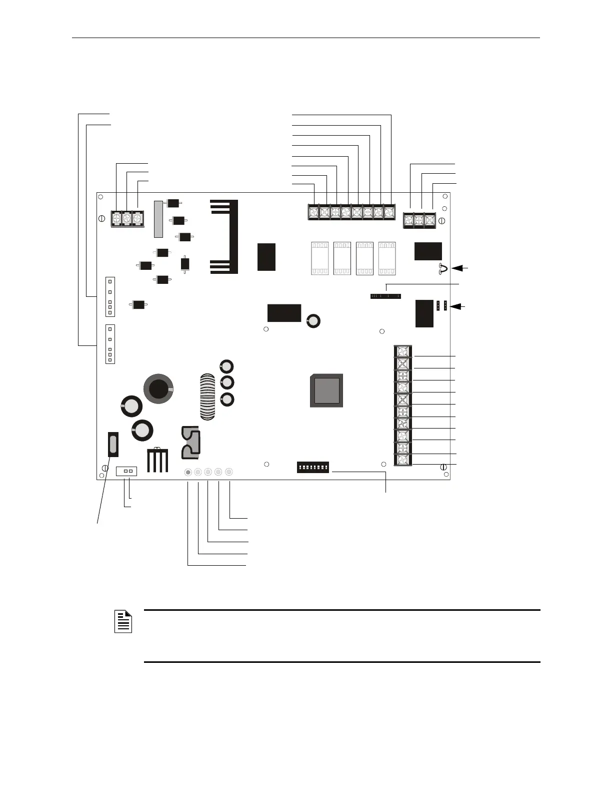
Figure 1.1 HPF24S Board Layout
- Aux. Common
+ Aux. 24 VDC*
- Control Input 2
+ Control Input 2
- Out Common
+ Out/Trouble Contact
- Control Input 1
+ Control Input 1
- Sync Input
+ Sync Input
NAC/Out 1 +
NAC/Out 1 -
NAC/Out 2 +
NAC/Out 2 -
NAC/Out 3 +
NAC/Out 3 -
NAC/Out 4 +
NAC/Out 4 -
Supervised,
Nonpower-limited
Earth
AC Neutral
AC Hot
Trouble Relay
Form-C Fail-safe
Nonsupervised
(shown energized)
Normally Open
Normally Closed
Common
JP1 Ground Fault
Detection
(cut to disable)
see Note at
bottom of the
page.
JP2 & JP3
Coded/Noncoded
Input Selection
JP4 Supervised
+ Battery
- Battery
18 AH, 24 VDC
Nonpower-
limited
LEDs
Charger Trouble/AC Loss (yellow)
NAC Trouble (yellow)
Battery Trouble (yellow)
Ground Fault (yellow)
AC Power (green)
SW1
Programming
DIP Switches
(change switch
settings only
when all power
(AC & DC) is
removed)
F1
Battery Fuse
15A, 32V
(Canadian version
is nonreplaceable
12 A, 32V)
Nonpower-limited
To Transformer #1
To Transformer #2
Auxiliary Output
500 mA Special
Application Power*
J3
ZNAC-4 Connector
*Note: Auxiliary Power
Output is power-limited
but not supervised
Power-limited, Supervised,
Special Application
in NAC Mode
24fs8brd.wmf
NOTE: Cutting Ground Fault jumper JP1 voids UL/NFPA Style/Class identifications for circuits
unless Ground Faults are being monitored by an FACP connected to the power supply. Cut
jumper JP1 only if a panel connected to the power supply is monitoring for Ground Faults or with
the approval of AHJ (Authority Having Jurisdiction).

 Loading...