ECS Series Emergency Communication System Installation Manual 151455
4-18
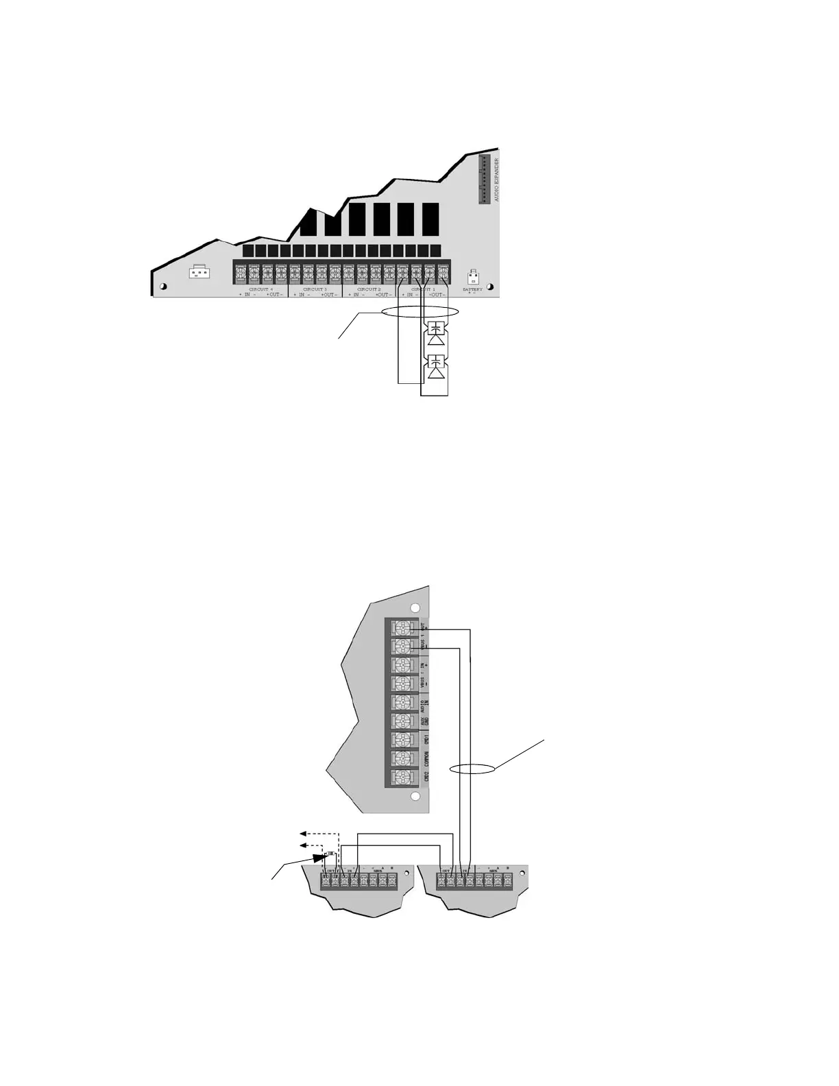
4.4.4.3 Class A Speaker Configuration
Figure 4-25 illustrates how to wire speakers to the control panel using Class A wiring.
Figure 4-25 Class A Speaker Configuration
4.4.5 VBUS Wiring
The VBUS is an analog voice bus that carries the recorded voice messages from the ECS-VCM or
ECS-NVCM to the ECS-50W’s, or the voice messages generated from a system microphone to the
ECS-50W’s. The maximum resistance on the VBUS is 20Ω.
Connect the VBUS from the ECS-VCM to the ECS-50W’s as shown in Figure 4-26 or ECS-NVCM as
shown in Figure 4-27.
Figure 4-26 VBUS Wiring with ECS-VCM
To Next ECS-50W
15kΩ EOL
ECS-VCM
ECS-50W
ECS-50W
Supervised
Power Limited
at Last panel
on the VBUS
VBUS Connections
3 Vrms, 5 mA max.
 Loading...


