ECS Series Emergency Communication System Installation Manual 151455
4-24
4.4.9 Calculating Current Draw and Standby Battery
This section helps you determine the current draw and standby battery needs for your installation (18
Ampere Hours max. will fit in cabinet). Complete the remaining instructions in Table 4-3.
Batteries larger than 18 AH will not fit in the main control cabinet, and must be housed in the RBB
Accessory Battery Cabinet. Maximum of 33 Amp Hours per system.
4.5 Installing the ECS-INT50W
This section provides information on how to install the ECS-INT50W for use with the ECS-Series
products.The ECS-INT50W Internal Amplifier can fit inside the IFP-300ECS or IFP-2000ECS cabinet.
It can also be adapted to fit into the ECS-2100ECS cabinet with the ECS-AMPMT mounting kit (sold
separately). It is used to amplify the audio message for distribution throughout the facility for the
Emergency Communication System.
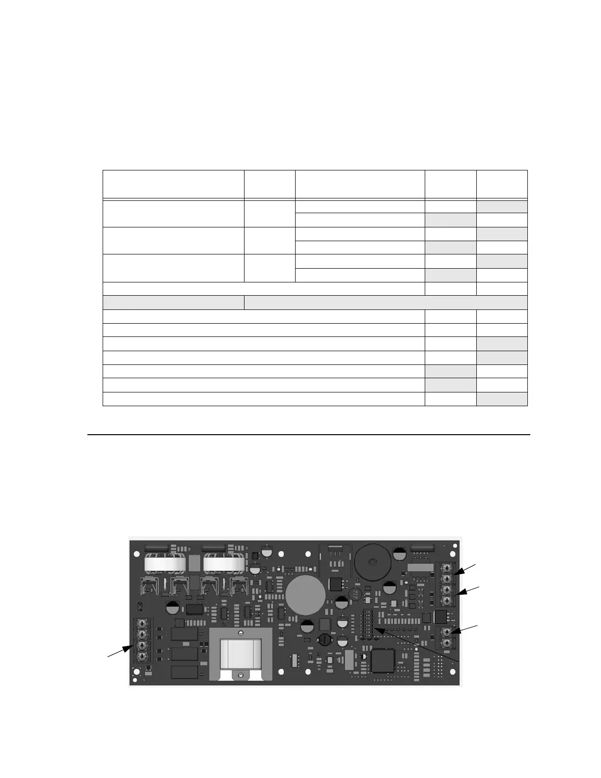
4.5.1 Board Layout & Mounting
Figure 4-33 Front View of ECS-INT50W
Table 4-3: Current Draw ECS-50W and ECS-CE4
Device
No. of
Devices
Current Per Device
Standby
Current
Alarm
Current
ECS-50W 25V 1 Standby: 85 mA 85 mA
Alarm: 525 mA 525 mA
ECS-50W 70.7V 1 Standby: 100 mA 100 mA
Alarm: 580 mA 580 mA
ECS-CE4 0 or 1 Standby: 20 mA 20mA
Alarm (All Channels): 180 mA 180 mA
A Current Subtotals: mA mA
Notification Devices Refer to device manual for number of devices and current ratings.
B Current Subtotals: mA mA
C Total current rating of all devices in system (Line B) X 0.001 A A
D Number of standby hours (24 or 60 for NFPA 72) H
E Multiply line C (standby current) and D:Total standby AH AH
F Alarm sounding period in hours (For example, 5 minutes = 0.0833 hours): H
G Multiply line C (alarm current) and F:Total alarm AH
AH
H Add lines E and G (AH = Ampere Hours):Total AH required AH
SBUS
VBUS
DIP Switch
Power
IN1 / OUT1

 Loading...


