N
KHF 1050 SYSTEM INSTALLATION MANUAL
LIST OF FIGURES
LOF-1
Revison 2 23-10-09 Apr/2006
Figure 1 - Typical System . . . . . . . . . . . . . . . . . . . . . . . . . . . . . . . . . . . . . . . . . . . . . . . 1
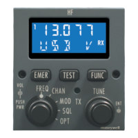
Figure 2 - PS440 Control Display Unit . . . . . . . . . . . . . . . . . . . . . . . . . . . . . . . . . . . . . . 2
Figure 3 - MC-850 Multifunction Control and Display Unit (MCDU). . . . . . . . . . . . . . . . 2
Figure 4 - RM-855 Radio Management Unit . . . . . . . . . . . . . . . . . . . . . . . . . . . . . . . . . 3
Figure 5 - Typical System Block Diagram . . . . . . . . . . . . . . . . . . . . . . . . . . . . . . . . . . . 6
Figure 6 - High Voltage Single Coupler Cable Assemblies . . . . . . . . . . . . . . . . . . . . . 20
Figure 7 - Coupler Cable Typical Connector Dimensions . . . . . . . . . . . . . . . . . . . . . . 21
Figure 8 - High Voltage Dual Coupler Cables . . . . . . . . . . . . . . . . . . . . . . . . . . . . . . . 21
Figure 1001 - KHF 1050 System Bench Test Harness . . . . . . . . . . . . . . . . . . . . . . 1013
Figure 1002 - PC Data Cable Connections . . . . . . . . . . . . . . . . . . . . . . . . . . . . . . . 1015
Figure 2001 - Typical Wing Tip “V” Antenna . . . . . . . . . . . . . . . . . . . . . . . . . . . . . . 2006
Figure 2002 - Typical Inverted “V” Antenna . . . . . . . . . . . . . . . . . . . . . . . . . . . . . . . 2007
Figure 2003 - Typical Long Wire Antenna . . . . . . . . . . . . . . . . . . . . . . . . . . . . . . . . 2008
Figure 2004 - Typical Short Wire to Vertical Stabilizer Antenna . . . . . . . . . . . . . . . 2009
Figure 2005 - Typical Short Wire to Wing Antenna . . . . . . . . . . . . . . . . . . . . . . . . . 2010
Figure 2006 - Typical Short Wire to Horizontal Stabilizer Antenna . . . . . . . . . . . . . 2010
Figure 2007 - Typical Shunt Leading Edge Antenna . . . . . . . . . . . . . . . . . . . . . . . . 2011
Figure 2008 - Typical Shorted Tranline or Towel Bar Antenna . . . . . . . . . . . . . . . . 2012
Figure 2009 - KAC 1052 Antenna Coupler Connector (J10521) Pin Configuration. 2017
Figure 2010 - KPA 1052 Power Amplifier Connector (J10524) Pin Configuration. . 2019
Figure 2011 - KRX 1053 Receiver/Exciter Connector (J10531) Pin Configuration . 2021
Figure 2012 - PS440 Control Display Unit Connector (J1) Pin Configuration . . . . . 2026
Figure 2013 - RM-855 RMU Connector (144J1) Pin Configuration . . . . . . . . . . . . . 2029
Figure 2014 - BNC Connector Assembly Procedure . . . . . . . . . . . . . . . . . . . . . . . . 2030
Figure 2015 - Crimping and Insertion/Extraction Tools . . . . . . . . . . . . . . . . . . . . . . 2031
Figure 2016 - Crimping and Insertion/Extraction Tools . . . . . . . . . . . . . . . . . . . . . . 2032
Figure 2017 - HF Antenna Kit PN 071-01214-0002. . . . . . . . . . . . . . . . . . . . . . . . . 2046
Figure 2018 - KAC 1052 Pressurization Valve . . . . . . . . . . . . . . . . . . . . . . . . . . . . 2054
Figure 2019 - KRX 1053 Adjustments . . . . . . . . . . . . . . . . . . . . . . . . . . . . . . . . . . . 2056
Figure 2020 - PS440 Control Display Unit Outline and Mounting . . . . . . . . . . . . . . 2061
Figure 2021 - MC-850 Multifunction Control and Display Unit Outline and Mounting 2063
Figure 2022 - RM-855 Radio Management Unit Outline and Mounting. . . . . . . . . . 2069
Figure 2023 - KAC 1052 Antenna Coupler Single Horizontal Outline and Mounting 2073
Figure 2024 - KAC 1052 Antenna Coupler Single Vertical Outline and Mounting . . 2075
Figure 2025 - KAC 1052 Antenna Coupler Dual Vertical Outline and Mounting . . . 2077
Figure 2026 - KAC 1052 Antenna Coupler Helicopter Outline and Mounting . . . . . 2079
Figure 2027 - KPA 1052 Power Amplifier Outline and Mounting . . . . . . . . . . . . . . . 2081
Figure 2028 - KRX 1053 Receiver/Exciter Outline and Mounting . . . . . . . . . . . . . . 2083
Figure 2029 - KHF 1050 HF System Interconnect. . . . . . . . . . . . . . . . . . . . . . . . . . 2085
Figure 2030 - KHF 1050 HF System Interconnect. . . . . . . . . . . . . . . . . . . . . . . . . . 2089
Figure 2031 - KHF 1050 HF Dual System Interconnect . . . . . . . . . . . . . . . . . . . . . 2093
Figure 2032 - KHF 1050 HF Dual System Interconnect . . . . . . . . . . . . . . . . . . . . . 2095
 Loading...


