GB-6
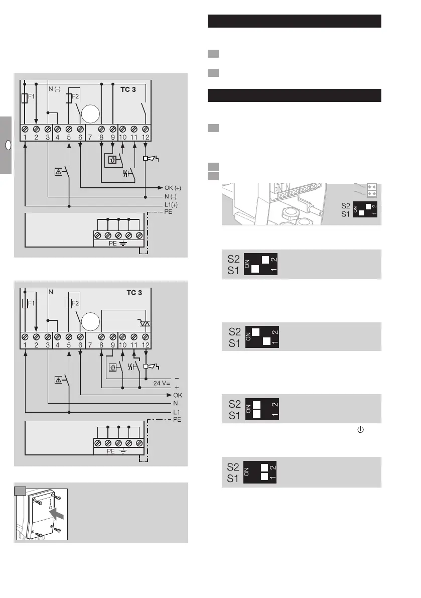
Connection diagram for TC
▷
The tightness test is carried out with the auxiliary
valves installed on TC 3 (pre-wired). The terminals
for the valve inputs remain vacant.
Mains voltage and control voltage:
24VDC/120VAC/230VAC
Mains voltage: 120VAC/230VAC,
control voltage: 24VDC
Finishing the wiring
9
Tightness test
▷ All new connections between the valve and the
TC must be checked for tightness.
Pressurize the system. Do not exceed the maxi-
mum inlet pressure.
Soap off pipe connections.
Setting the test instant
▷
The test instant (MODE) can be set using two
DIP switches.
Disconnect the unit from the electrical power
supply.
▷
Before opening the unit, the fitter should ground
himself.
Unscrew the housing cover.
Set the test instant to Mode 1, 2 or 3.
5s
▷ Mode 1: test before burner start-up with incom-
ing thermostat/start-up signalϑ (factory setting).
Mode 1
▷ Mode 2: test after burner run when the thermo-
stat/start-up signal ϑ drops and after switching
on the mains voltage.
▷ The tightness test also starts after a reset.
Mode 2
▷
Mode 3: test with incoming thermostat/start-up
signal ϑ before burner start-up and when the
thermostat/start-up signal ϑ drops after burner
run.
Mode 3
▷ Invalid switch setting: no function. The
LED
is permanently red, see page8 (Assistance
in the event of malfunction).
▷
Continue on page 7 (Setting measurement
time tM).
 Loading...


