GB-9
?
yellow and permanently lit?
! Safety interlock input signal is interrupted, no
voltage at terminal 5. The tightness test is still
being carried out. No enable signal is issued to
the automatic burner control unit.
• Check safety interlocks.
! Fuse F2 defective.
• Replace fuse F2, see page9 (Replacing the
fuse).
?
yellow and flashing?
! Permanent remote reset. The remote reset signal
has been active for more than 10s.
• The warning signal is cancelled once the remote
reset signal to terminal11 has been removed.
?
red and permanently lit?
! Incorrect jumper/DIP switch setting.
• Correct jumper and DIP switch setting, see
pages 7 (Setting measurement time tM)
and6 (Setting the test instant). Then press
the reset button.
! Internal error.
• Remove the unit and return it to the manufacturer
for inspection.
?
red and flashing?
! Too frequent burner start commands. The TC
performs a fault lock-out. The start commands
are limited to 5x in 15minutes.
▷
As long as this limit is not exceeded, another
start-up attempt is possible after three further
minutes. If a tightness test is completed, the
counter which limits the number of start com-
mands is reset.
• Then press the reset button.
! Too many remote resets. More than 5resets
have been conducted within the last 15minutes,
either automatically or manually.
! Consecutive fault caused by a previous fault
whose actual cause has not been remedied.
• Pay attention to previous fault messages.
• Remedy cause. Then press the reset button.
?
or
red and permanently lit?
! The valve is leaking. The TC performs a fault
lock-out.
• Replace the valve.
! Wiring of the TC to the valves is faulty.
• Start the program and observe the interspace
pressurep
z
. The pressure must change during
the TEST phase. Check the wiring.
! Inlet pressurep
u
<10mbar.
• Provide the min. inlet pressure of 10mbar.
! Interspace pressurep
z
cannot be reduced.
• The volume downstream of the valve on the
burner side must be 5times higher than the
volume between the valves and atmospheric
pressure must prevail.
! The measurement time t
M
is too long.
• Readjust t
M
, see page 7 (Setting measure-
ment time tM).
?
and
red and permanently lit?
! During the tightness test, the TC has determined
that inlet valve1 and outlet valve2 have been
reversed (fault lock-out).
• Check the wiring. Then press the reset button.
? No LED lit even though mains voltage ap-
plied?
! Fuse F1 defective.
• Replace fuse F1, see page9 (Replacing the
fuse).
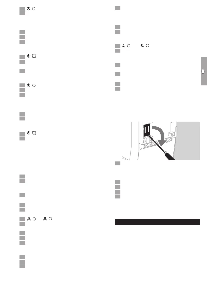
Replacing the fuse
▷
The fuses F1 and F2 can be removed for in-
spection.
▷ Insert a screwdriver into the opening in the con-
tact guard to prise out the fuse.
Disconnect the TC from the electrical power
supply.
▷
Before opening the unit, the fitter should ground
himself.
Unscrew the housing cover.
Remove fuse F1 or F2.
4 Check function of fuse.
5 Replace the defective fuse.
▷
When replacing the fuse, use only the approved
fuse type, see page10 (Technical data).
▷ Restart the TC, see page8 (Commissioning).
Maintenance
Tightness controls TC require little servicing. We rec-
ommend carrying out a function check once a year
or twice a year in the case of biogas.
 Loading...


