– 67 –
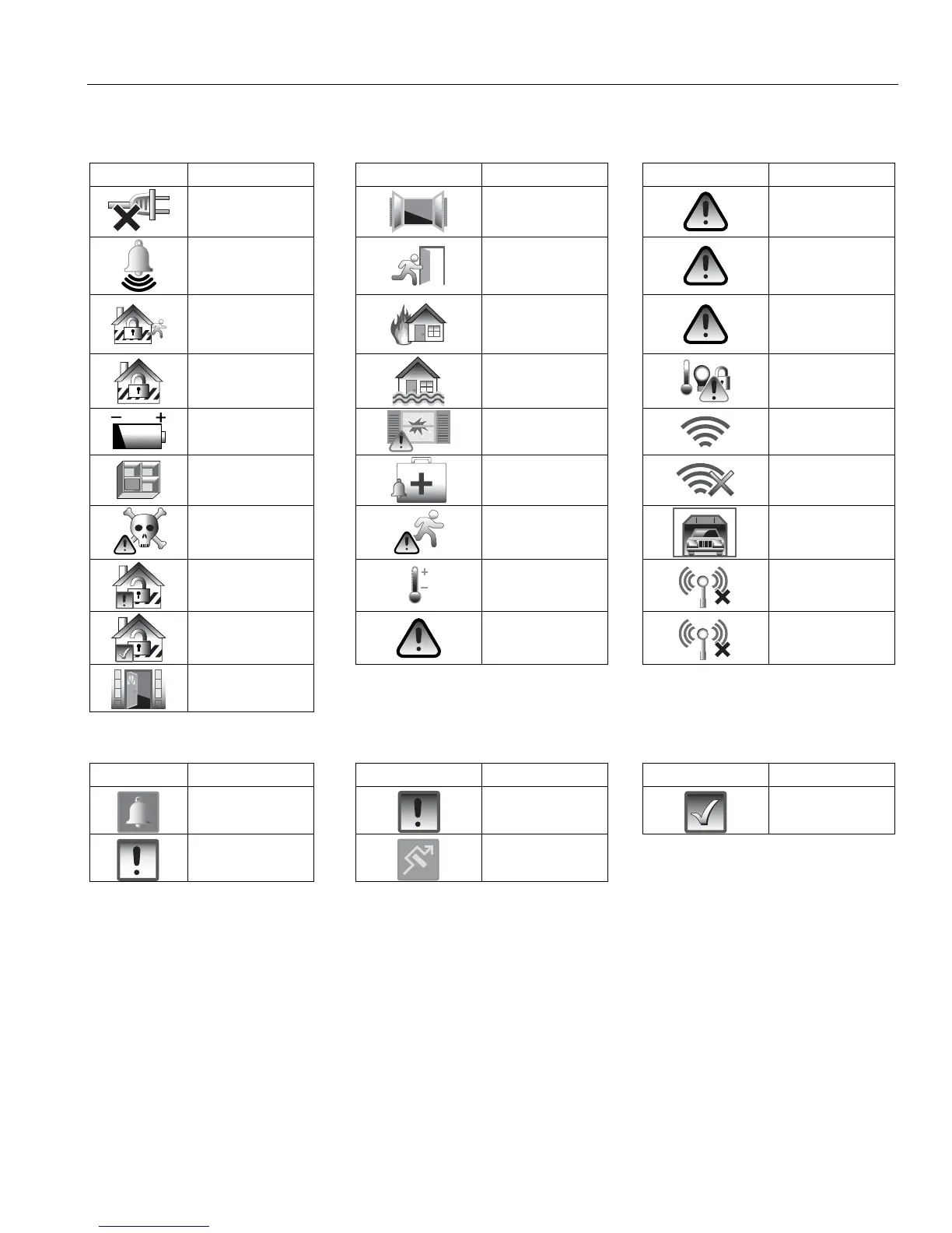
SUMMARY OF AUDIBLE & VISUAL NOTIFICATIONS
System Displays
The following icons will be displayed on the Security Screen along with specific zone status information (if
applicable) to indicate system status.
DISPLAY
DEFINITION
DISPLAY
DEFINITION
DISPLAY
DEFINITION
AC Loss
Window Open
Cover
Tamper
Alarm
(intrusion)
Exit Active
Trouble
Armed Away
Fire
OR
Heat Sensor
90 RF Jam
Armed Stay
Flood
Automation
(Z-Wave Node
Failed)
Battery Low
Glass Break
WiFi source
present
Check Zones
Medical Alarm
No WiFi source
CO Alarm
Motion
Fault *
Garage Door
Disarmed Not
Ready to Arm
Temperature
94 Phone
Line Cut
Disarmed
Ready to Arm
Reporter
Failure
103 Comm.
Trouble
Door Open
Zone Status Icons
The following icons may be displayed on the Zone Status screen.
ICON
DEFINITION
ICON
DEFINITION
ICON
DEFINITION
Alarm
Trouble (red)
Ready
Fault (Yellow)
Bypass
LED Status
Armed LED (Red): ON = System armed
OFF = System disarmed
Blinking = System armed, but a fault exists or alternating with Ready LED when Two Way Voice
(VOX or Talk), speaker phone or programming mode is active.
Ready LED (Green): ON = System disarmed, ready to arm
Blinking = System disarmed, not ready to arm (a fault exists) or alternating with Armed LED
when Two Way Voice (VOX or Talk), speaker phone or programming mode is active.
Note: When the system is armed, the Ready LED turns off.
 Loading...