- 8 -
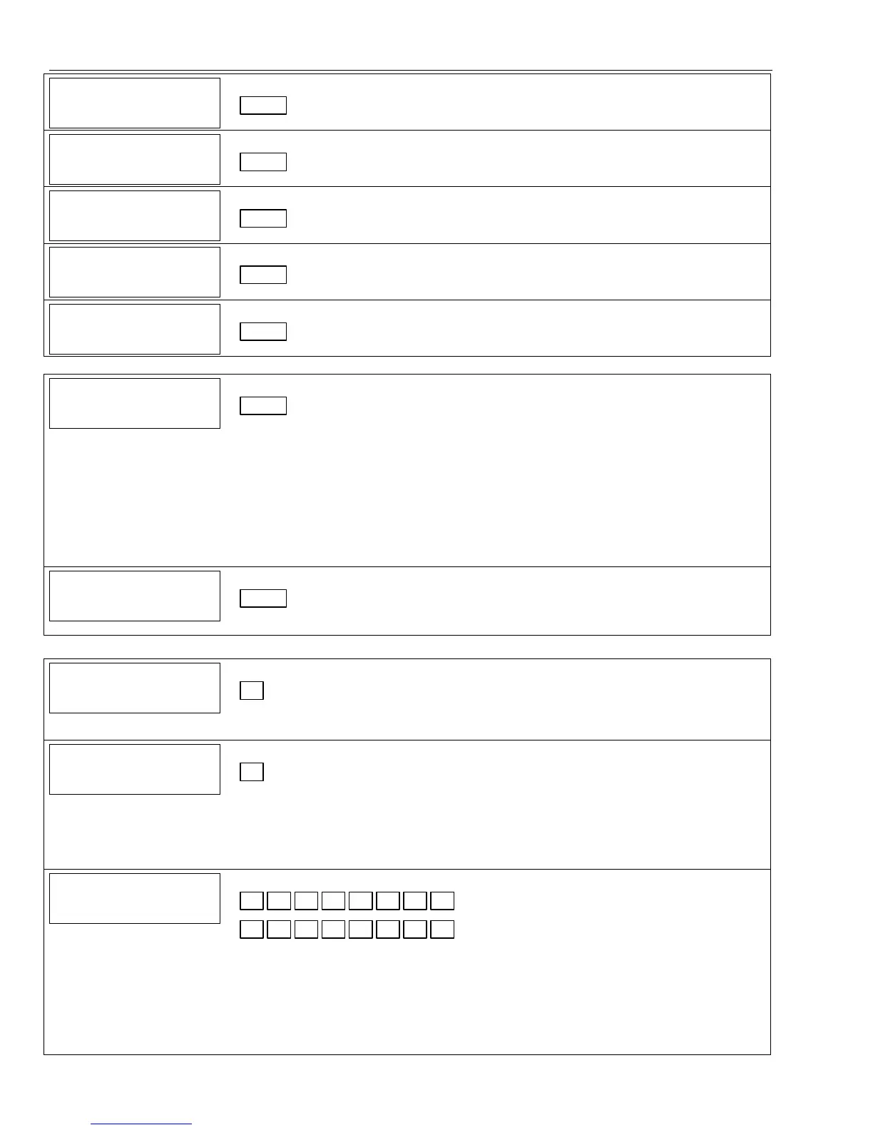
Data Field Display Function& Programming Options [ ] = Programmed Table 1 Default Values
72
7272
72
BYPASS
BYPASSBYPASS
BYPASS
RES
RES RES
RES
REP
REPREP
REP
Bypass Restore Report Code
|
[0,0]
73
7373
73
AC
AC AC
AC
RESTORE
RESTORERESTORE
RESTORE
REP
REP REP
REP
AC Restore Report Code
|
[0,0]
74
7474
74
LO
LO LO
LO
BAT
BATBAT
BAT
RES
RES RES
RES
REP
REP REP
REP
Low Bat Restore Report Code
|
[1,0]
75
7575
75
RF
RFRF
RF
LOBAT
LOBAT LOBAT
LOBAT
RES
RESRES
RES
REP
REP REP
REP
RF Transmitter Low Battery Restore Report Code
|
[1,0]
76
7676
76
TEST
TEST TEST
TEST
RES
RES RES
RES
REPORT
REPORTREPORT
REPORT
Test Restore Report Code
|
[0,0]
DYNAMIC SIGNALING FIELD (✻77)
77
7777
77
DYNAMIC
DYNAMIC DYNAMIC
DYNAMIC
SIG
SIG SIG
SIG
OPTS
OPTSOPTS
OPTS
Dynamic Signaling Options
|
[0, 0]
1st Entry (delay before switch CS reporting path)
0 = Redundant
reporting on dialer
and LRR/IP device
1 = 15 seconds
2 = 30 seconds
3 = 45 seconds
4 = 60 seconds
5 = 75 seconds
6 = 90 seconds
7 = 105 seconds
8 = 120 seconds
9 = 135 seconds #1
= 150 seconds
#11 = 165 seconds
#12 = 180 seconds
#13 = 195 seconds
#14 = 210 seconds
#15 = 225 seconds
2nd Entry
0 = Primary Dialer
Preferred Channel
1 = LRR/IP
Preferred Channel
2 = LRR/IP
reporting only
78
7878
78
PROG TONE GEN TM
PROG TONE GEN TMPROG TONE GEN TM
PROG TONE GEN TM
Programmable Tone Generation Time
|
[0, 0]
00 = Disabled; 01-09 = 100-900 ms; 10-99 = 1.0 – 9.9 secs
OUTPUT AND SYSTEM SETUP (✻80, ✻81, ✻83–✻85) See Procedures later in this manual.
86
8686
86
MULTI
MULTIMULTI
MULTI-
--
-MODE
MODE MODE
MODE
EMAIL
EMAILEMAIL
EMAIL
Multi-Mode (E-Mail Notification)
[0]
0 = Disable multi-mode devices; 1 = Enable multi-mode device address #6 only;
2 = Enable multi-mode device address #7 only; 3 = Enable multi-mode addresses
87
8787
87
AUX
AUX AUX
AUX
FUNC
FUNCFUNC
FUNC
1BTN
1BTN 1BTN
1BTN
PG
PG PG
PG
Aux Function/ 1-Button Paging
[0]
0 = Aux key performs defined function (macro);
1 = Aux key sends message to pager or voice message to follow me system phone
number.
If 1, you must also select an option 6-9 in field ✻49 for the pager or 10-13 for the follow me
system announcement.
8
88
88
88
8
P
PP
PA
AA
AG
GG
GER CHARACTERS
ER CHARACTERSER CHARACTERS
ER CHARACTERS
Pager Characters
Up to 16 digits can be entered that will appear in front of the 7-digit pager message sent by
the control. Refer to the Installation Instructions (fields ✻87, ✻88 and ✻49) for full
descriptions of the paging feature. You do not need to fill all 16 digits (press [✻] to
advance to next field).
To clear entries, enter ✻88✻. To enter “✻” = [#] + [11]; To enter “#” = [#] + 12]; To
enter 2-second pause = [#] + [13] (some pagers require an additional delay [pause] in
order to receive the entire message)
 Loading...