35 AND 70 LB-IN. NON-SPRING RETURN DIRECT COUPLED ACTUATORS
63-2209—8 10
OPERATION
VAV Systems
VAV systems control the temperature within a space by
varying the volume of supply air temperature. The system
delivers air to the space at a fixed temperature. The space
thermostat controls the volume of supply air by modulating the
supply air damper. When full heating and cooling flexibility is
required in a zone, it is handled by the air temperature
system, or with reheat capability in the air terminal units. As
individual zones shut down, a central duct static pressure
controller regulates the total air flow in the system. The fan
system is sized to handle an average peak load, not the sum
of the individual peaks. As each zone peaks at a different time
of day, extra air is borrowed from the off-peak zones. This
transfer of air from low-load to high-load zones occurs only in
true VAV systems.
In pressure independent systems, individual zone airflow
sensors maintain the zone air flow rate independent of
fluctuation in the total system pressure. Pressure independent
systems, when used with controllers such as the W7620, can
react faster to changes in air flow demand; therefore, these
systems can use the faster 90-second models.
Pressure dependent systems do not incorporate an individual
zone air flow sensor and depend on a stable system pressure
to maintain flow. These systems require slower actuators such
as the seven-minute models that are typically controlled by
spdt floating wall thermostats.
The T641 is a mercury bulb floating-control type thermostat
designed for use with the seven-minute model on pressure-
dependent systems (see Fig. 16 and 17).
The T6984 is an electronic floating-control thermostat
designed for use with the 90-second and seven-minute
models (see Fig. 18).
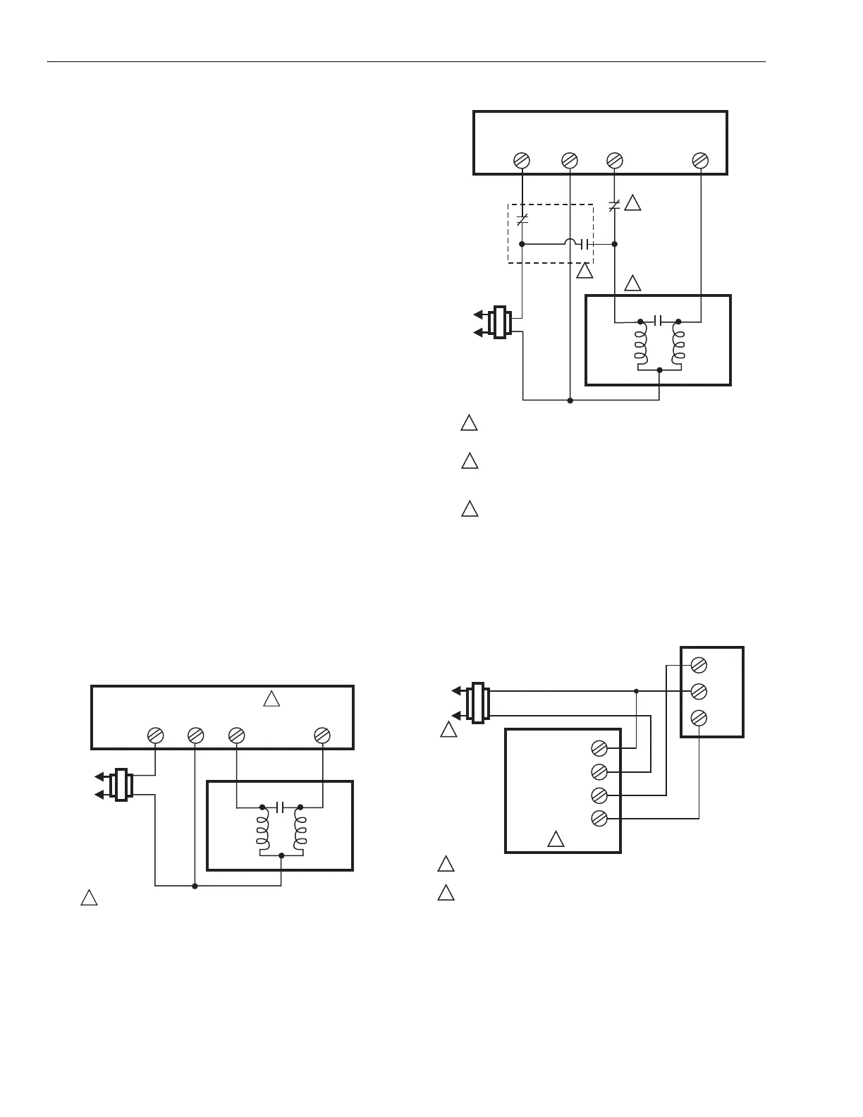
Fig. 16. T641A controlling ML6161 or M6174 Actuator.
Fig. 17. Minimum position set with auxiliary switch
contacts, override provided by fire and alarm contacts.
Fig. 18. T6984A controlling ML6161 or ML6174 Actuator
for cooling or heating application.
1
1
RCY W
T641A THERMOSTAT
120
VAC
SYSTEM
TRANSFORMER
24
VAC
CCW
CW
PHASE SHIFT CAP.
DRIVE
CCW
WINDING
DRIVE
CW
WINDING
COM
COMMON
AS SHOWN, T641 MAKES R-Y CONTACTS TO DRIVE ACTUATOR
CCW, AND MAKES R-W CONTACTS TO DRIVE ACTUATOR CW.
M18021
ML6161, ML6174
ACTUATOR
1
1
2
3
3
2
RCY W
T641A THERMOSTAT
1K
120
VAC
SYSTEM
TRANSFORMER
24 VAC
CCW
CW
PHASE SHIFT CAP
DRIVE
CCW
WINDING
DRIVE
CW
WINDING
COM
ML6161, ML6174
ACTUATOR
COMMON
USE NC CONTACT OF AUXILIARY SWITCH (PIN 201052A).
CONTACT OPENS WHEN ACTUATOR DRIVES CLOSED (CCW)
TO CAM SETTING POSITION.
USE SPDT RELAY OUTPUTS FROM FIRE AND ALARM
SYSTEM, OR OVERRIDE SYSTEM, AS DRAWN. THIS
OVERRIDES MINIMUM POSITION LIMITATION, AND
DRIVES ACTUATOR FULLY CCW.
AS DRAWN, ACTUATOR OPENS DAMPER TO CW ROTATION.
TO OPEN DAMPER TO CCW, REVERSE CCW AND CW
CONNECTIONS AT ACTUATOR. THIS ALSO CAUSES
ALARM CONDITION TO DRIVE ACTUATOR TO FULLY CW.
M18022
1
1
2
2
L1
(HOT)
24 VAC
POWER SUPPLY. PROVIDE DISCONNECT MEANS AND
OVERLOAD PROTECTION, AS REQUIRED.
T6984A SHOWN WIRED FOR COOLING ONLY. TO WIRE FOR
HEATING ONLY, REVERSE OPEN AND CLOSE CONTACTS.
M18023
ML6161, ML6174
CW
COM
CCW
L2
COMMON
24 VAC
MOTOR CLOSE
MOTOR OPEN
T6984A

 Loading...


