35 AND 70 LB-IN. NON-SPRING RETURN DIRECT COUPLED ACTUATORS
63-2209—8 8
IMPORTANT
Run an entire check of the operation after completing
this procedure.
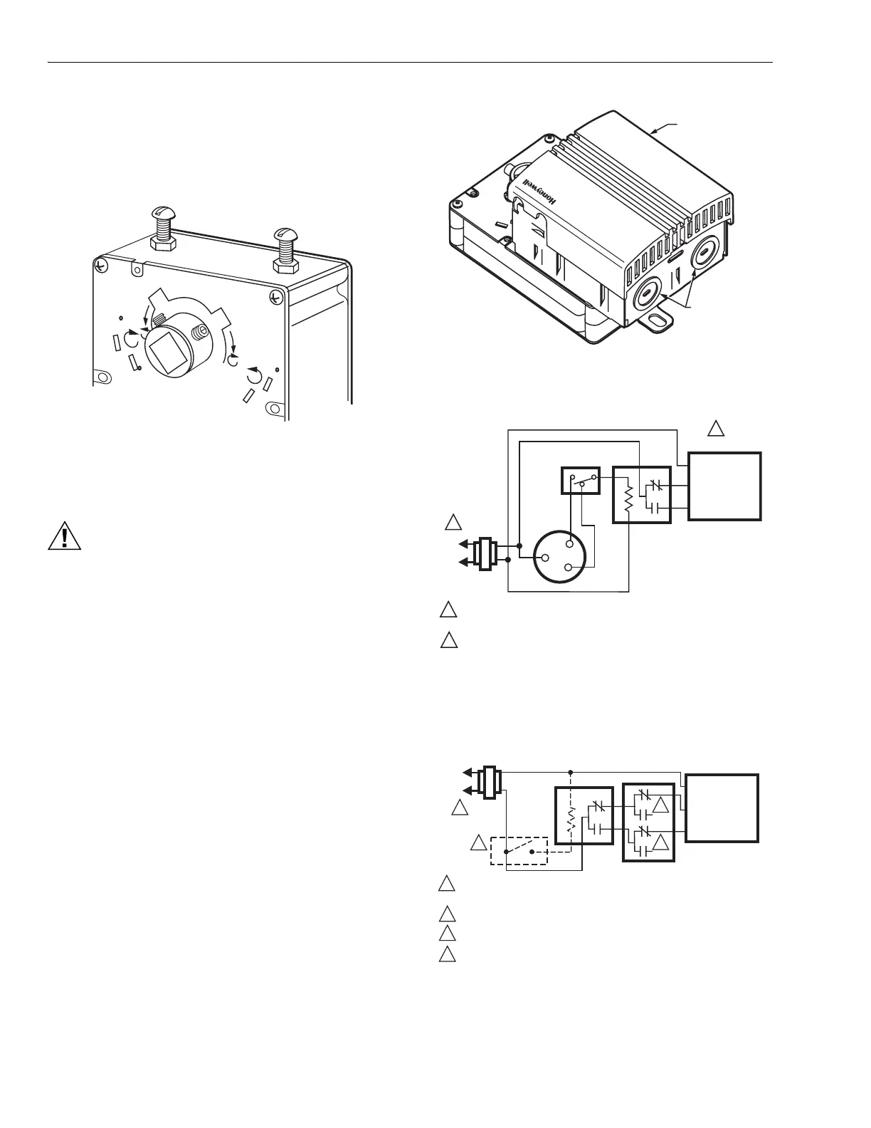
Fig. 9. Setscrew location for ML6161 and ML6174.
Wiring
CAUTION
Electrical Shock or Equipment Damage Hazard.
Can shock individuals or short equipment
circuitry.
Disconnect all power supplies before installation.
Actuators with auxiliary switches can have more than
one disconnect.
All wiring must comply with local electrical codes, ordinances
and regulations. Voltage and frequency of the transformer
used with the actuator must correspond with the
characteristics of both the power supply and the actuator.
Screw terminals are provided for easy hookup. See Fig. 11
through 14 for typical wiring hookups.
Connecting Wiring to Conduit Cover Actuators (Fig.
10)
1. Remove the cover from the actuator by lifting the top
and pivoting the cover to the rear of the actuator.
2. Remove the conduit knockouts with a flat-bladed screw-
driver. Discard the knockouts.
3. Install the conduit connector.
4. Run the connecting wire through the conduit connector,
strip the wire ends (if necessary) and connect to the
CW, COM and CCW terminals using Fig. 11 through 14,
Fig. 16 through 20, or the control manufacturer
instructions.
5. Apply power to the actuator.
6. After operational checkout, replace the cover by
reversing the procedure outlined in step 1.
Fig. 10. Conduit cover for ML6161C,D
and ML6174C,D DCA.
Fig. 11. ML6161 or ML6174 used with T87F in
heating-only or cooling-only application.
NOTE: See Fig. 12 for the 201052B Auxiliary Switch wiring.
Fig. 12. 201052B Auxiliary Switch wiring.
M10247
60
45
45
60
THIS SETSCREW
CORRESPONDS WITH
CLOSING IN THE
CW DIRECTION
THIS SETSCREW
CORRESPONDS WITH
CLOSING IN THE
CCW DIRECTION
COVER
M10075
CONDUIT
KNOCKOUTS
M18019
EXTERNAL
SWITCH
R
W
Y
T87F
R8222
RED COM
BLUE CW
WHITE CCW
L1
(HOT)
L2
1
1
2
2
POWER SUPPLY. PROVIDE DISCONNECT MEANS AND OVERLOAD
PROTECTION AS REQUIRED.
AUXILIARY SWITCHES ARE REQUIRED TO TURN OFF THE MOTOR
AT EACH END OF THE STROKE.
ML6161, ML6174
M17350
SPDT
CONTROL
ON/OFF
CONTROL
RED COM
BLUE CW
WHITE CCW
L1
(HOT)
L2
1
1
4
2
3
2
3
4
POWER SUPPLY. PROVIDE DISCONNECT MEANS AND OVERLOAD
PROTECTION AS REQUIRED.
SET SWITCH TO CLOSE WHEN STROKE REACHES FULL CW POSITION.
SET SWITCH TO CLOSE WHEN STROKE REACHES FULL CCW POSITION.
ON-OFF CONTROL REQUIRES AN R8222 SPDT RELAY IN PLACE OF THE
SPDT CONTROL.
ML6161, ML6174
201052B

 Loading...


