35 AND 70 LB-IN. NON-SPRING RETURN DIRECT COUPLED ACTUATORS
63-2209—8 6
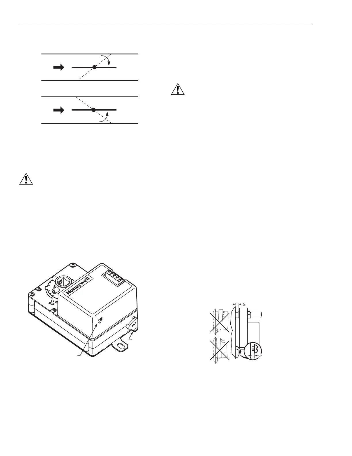
Fig. 4. Determining direction damper
shaft rotates when opening.
Manual Operation (Declutch)
CAUTION
Product Damage Hazard.
Do not use manual declutch without supporting
the load.
Support actuator load independently immediately
before and during use of manual declutch lever.
Manual declutch capability is available on some actuators.
Use the manual declutch lever to manually adjust the actuator
setting. Fig. 5 shows the location of the manual declutch lever.
To operate, push the lever in the direction of the arrow on the
lever cover.
Fig. 5. Location of manual declutch lever.
Installation
After determining the direction of the shaft rotation (cw or
ccw), install the device. For valve linkage mounting, refer to
the instructions shipped with the linkage. For damper
mounting, proceed as follows:
1. Place the actuator onto the damper shaft.
CAUTION
Equipment Damage Hazard.
Improper range stop selection can damage
light-duty dampers.
Be sure to select the proper range stop.
2. If the angle of the damper opening is either 45° or 60°,
close the actuator using the manual declutch:
a. Disengage the hub using the declutch lever; see
Manual Operation (Declutch) section.
b. Rotate the hub until the actuator gear train passes
the proper 45° or 60° setting. (Do not insert the pin
until after the actuator passes this point.)
c. Release the declutch lever.
NOTE: Dampers with 90° stroke do not require the
range stop pin.
3. Insert the range stop pin into the appropriate (cw or
ccw) 45° or 60° slot. The range stop pin clips into its
final position only after the pin passes through both
actuator plates (see Fig. 7). The range stop pin should
snap into position and not be removable manually
(see Fig. 8).
IMPORTANT
Do not fully tighten the mounting screw; the actuator
must be allowed to float.
4. With the actuator placed in its final position, fix the
mounting tab in position with a 1/4 in. screw or pin. See
Fig. 6.
5. Position the damper in the open position and securely
tighten the Allen screws into the damper shaft.
Fig. 6. Proper actuator mounting to prevent rotation.
IR
FLOW
IR
FLOW
CW TO OPEN, CCW TO CLOSE
CCW TO OPEN, CW TO CLOSE
M2067BB
TYPE A DAMPER
TYPE B DAMPER
M10076B
MANUAL
DECLUTCH
LEVER
ROTATION
REVERSAL SWITCH
60
60
M20884
1MM
(1/32 IN.)
1MM (1/32 IN.)

 Loading...


