35 AND 70 LB-IN. NON-SPRING RETURN DIRECT COUPLED ACTUATORS
7 63-2209—8
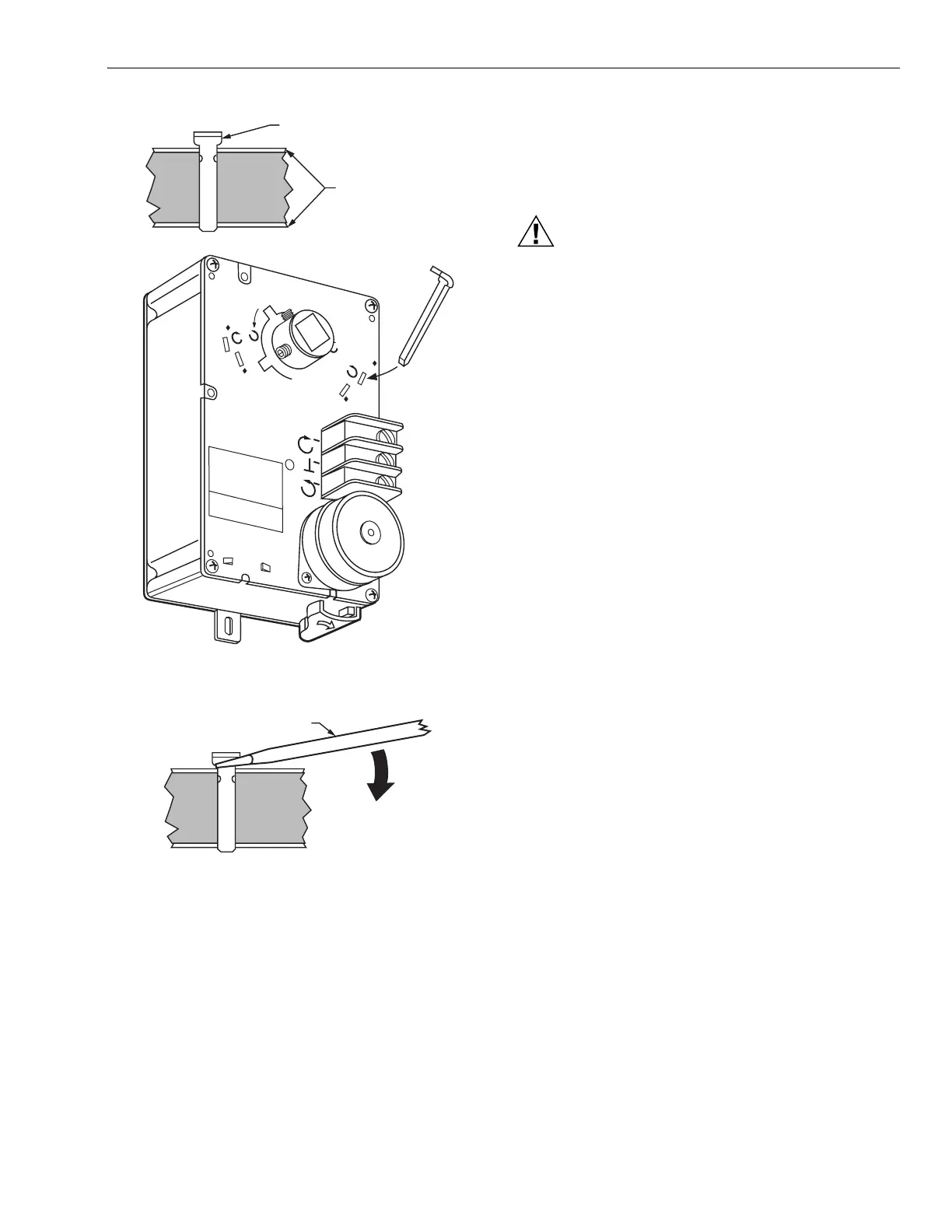
Fig. 7. Range stop pin properly inserted.
Fig. 8. Lifting range stop pin out of its slot.
Minimum Position Setscrew
Certain ML6161, ML6174 and all ML7161, ML7174 models
are equipped with two tapped holes located in the plastic
housing at the top of the actuator. These holes can be used
with the minimum position setscrew and locknut inside the
4074ENJ Bag Assembly (see Fig. 9). The setscrew provides
for a 0° to 30° minimum position adjustment.
NOTE: Before starting operation, note that the 1/4 in.
minimum position setscrew limits closing motion,
while the range stop pin limits opening motion.
1. Determine the direction of the desired closing rotation.
2. Move the actuator to the position fully opposite the
desired closing rotation (if cw closing rotation is desired,
move the actuator to the full ccw position).
3. Determine the correct hole for the setscrew using Fig. 9
and the results of step 1.
CAUTION
Equipment Damage Hazard.
Improper hub positioning or hole selection can
permanently damage the device.
Avoid backdriving the actuator with the setscrew.
4. Remove the red cap from the desired hole. Leave the
other cap in position. The caps ensure that dust and
other impurities do not enter the gear train through
unused holes.
5. Thread the locknut fully onto the 1/4 in. setscrew.
6. Insert the setscrew into the desired hole, turning
clockwise until resistance is encountered or the locknut
contacts the housing.
7. If resistance is met before the setscrew is fully inserted,
stop and review the initial setup procedures as detailed
in steps 1 through 3.
8. Determine the angle of minimum position required for
the application. With the setscrew fully inserted, the
minimum position is 30°. With the setscrew fully out, the
minimum position is 0°.
9. Using the conversion of approximately 1.7 angular
degrees per turn of the setscrew, back the screw out of
the housing and stop slightly short of the calculated
position. This allows the setscrew to be set accurately
while taking air flow measurements.
IMPORTANT
After initiating step 10, the setscrew cannot be turned
into the housing without returning the actuator to the
fully open position (as determined in step 1). The
actuator follows the setscrew without damaging the
housing only when backed out of the housing (turned
ccw).
10. Rotate the actuator to minimum position using the
manual declutch; see Manual Operation (Declutch)
section.
11. With the actuator at minimum position, adjust the
position more accurately using air flow measurements.
NOTES:
1. After each adjustment, ensure the actuator is
completely stopped before proceeding with the
next adjustment.
2. To reduce the minimum position, turn out the set-
screw (ccw). The actuator then drives toward the
closed position.
3. Turning the setscrew in (cw) damages the
actuator housing.
4. If the device is too far closed, return to step 1.
12. When proper air flow is achieved, loosen the locknut
from the setscrew until it contacts the actuator housing,
then turn it an additional 1/8 turn to lock the setscrew in
place.
60
45
45
60
CW
CCW
COM
RANGE STOP PIN
ACTUATOR PLATES
M10246A
SCREWDRIVER
M2065
 Loading...


