42 NFW-50X Manual — P/N LS10129-001NF-E:C 7/25/2018
Installation Optional Module Installation
Specifications
• Max. ANN-BUS Voltage: 24 VDC
• Max. Current:
Alarm: 68 mA
Standby: 28 mA
• Operating Temperature: 32°F to 120°F (0°C to 49°C)
• For indoor use in a dry location only
Mounting/Installation
The N-ANN-LED Module is supplied with a metal backbox, mounting bracket, and cover. Refer to the N-ANN-LED Installation Docu-
ment #53317 for more information.
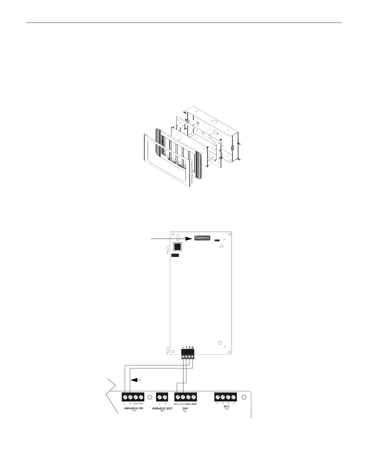
N-ANN-LED Board Layout and Connection to FACP
Figure 2.27 illustrates the N-ANN-LED board showing locations of screw terminals for connection to the FACP and the DIP switches
for selecting the ANN-BUS ID number.
Figure 2.26 Exploded View of N-ANN-LED
a
n
n
-
l
e
d
.
w
m
f
TB1
J1
SW1
JP2
ANN-BUS
1 2 3 4 5 6 7 8
+ -
Figure 2.27 N-ANN-LED Board Layout and Connection to FACP
NFW-50X
N-ANN-LED
Primary ANN-BUS
-24 VDC
+24 VDC
ANN-BUS and power wiring are
supervised and power-limited
e
s
5
0
t
o
l
e
d
.
w
m
f
ANN-BUS (ID#)
Address DIP switch

 Loading...


