UDACT-2 — Instruction Manual P/N 54089:B3 10/29/2019 21
Relay Driver (Auxiliary Output) Connections - TB4 Installation and Wiring
When the UDACT-2 is programmed for “Receive/Transmit”, EIA-485 supervision and UDACT-2 trouble status are automatically han-
dled by the host control panel. The relay output may, however, be used for UDACT-2 communications failure if desired.
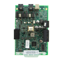
Figure 2.16 Relay Driver Connections
Relay Energized LED
DPDT Contacts
10 Amps @115 VAC
SPDT Contacts
10 Amps @115 VAC
Udact-2 relays.wmf
Relay Energized LED
UDACT-2
MR-101/C
MR-201/C
UDACT-2
SLC from FACP
Continuation of SLC
FMM-1*
47K EOL Resistor
(included)
Udact-2 monitr.wmf
(MR-201/C may be used)
*If the SLC device does not match the one in this figure, refer to the SLC manual appendix, which contains wiring conversion charts for type V and type H modules.
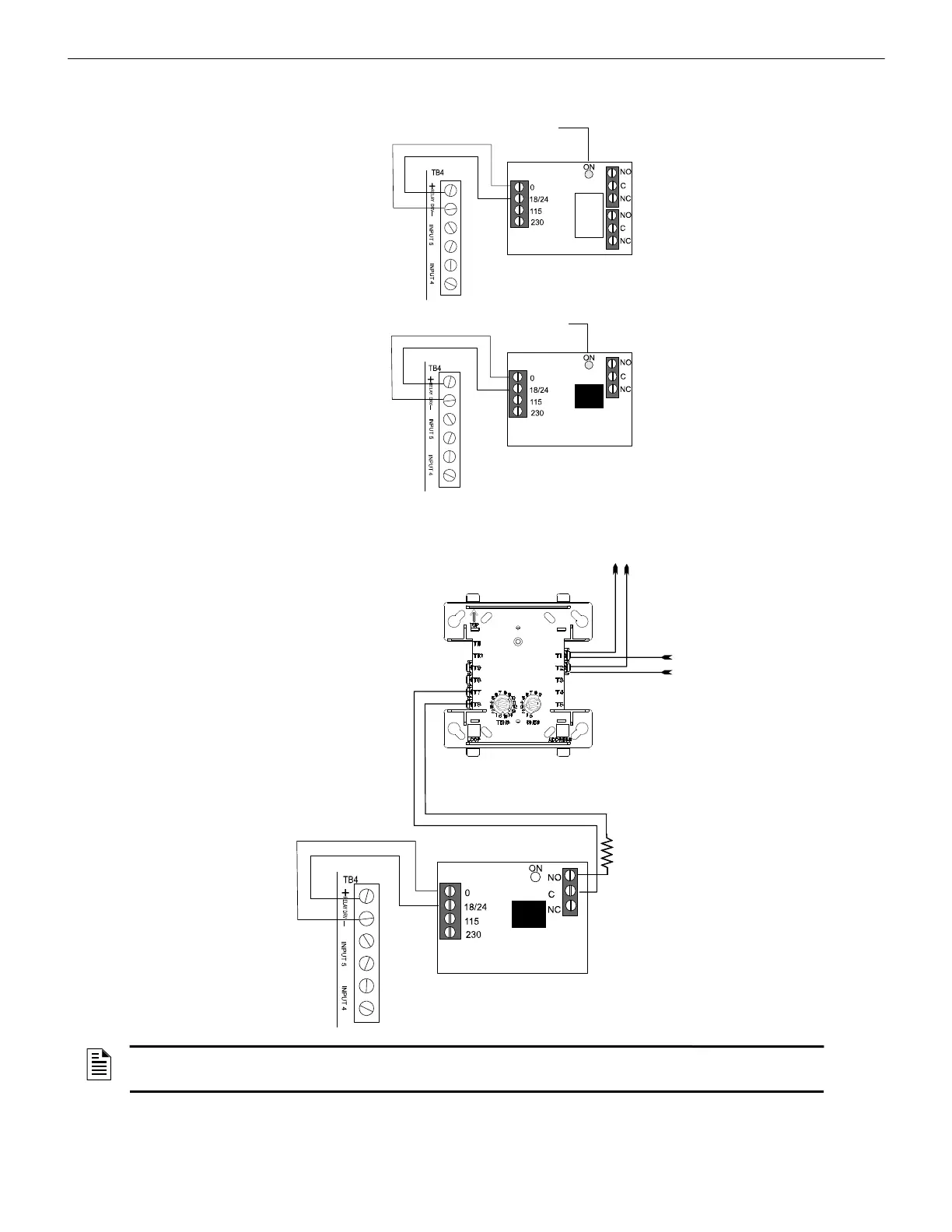
Figure 2.17 Monitoring for UDACT-2 Trouble
NOTE: An FMM-1 Monitor Module is used to supervise the Normally Open output of MR-101/C. If a Trouble Condition or
Communication Failure occurs on the UDACT-2, the MR-101/C relay contact will close, causing the FMM-1 to transmit a
trouble condition to the FACP.
UDACT-2
MR-101/C
Note: The NO contact is
used, as the relay is
normally energized to
ensure a trouble is
generated when power to
the unit is lost.
 Loading...