4 PW-7000 Output Module (PW7K1OUT) Installation Guide, Document 800-25675V1
* = Default
LED Operation
The Output Board uses two onboard LEDs to provide status information during the
power-up sequence and during normal operation.
Table 3: LED Settings
In addition to the status LEDs, there are 16 additional LEDs on board for relay sta-
tus. When any relay is energized or ON, its corresponding status LED turns ON
also. The LED remains ON for as long as the relay is energized. The assignment for
each relay status LED is shown in the following table.
Table 4: Relay LEDs: 0-7
Table 5: Relay LEDs: 8-15
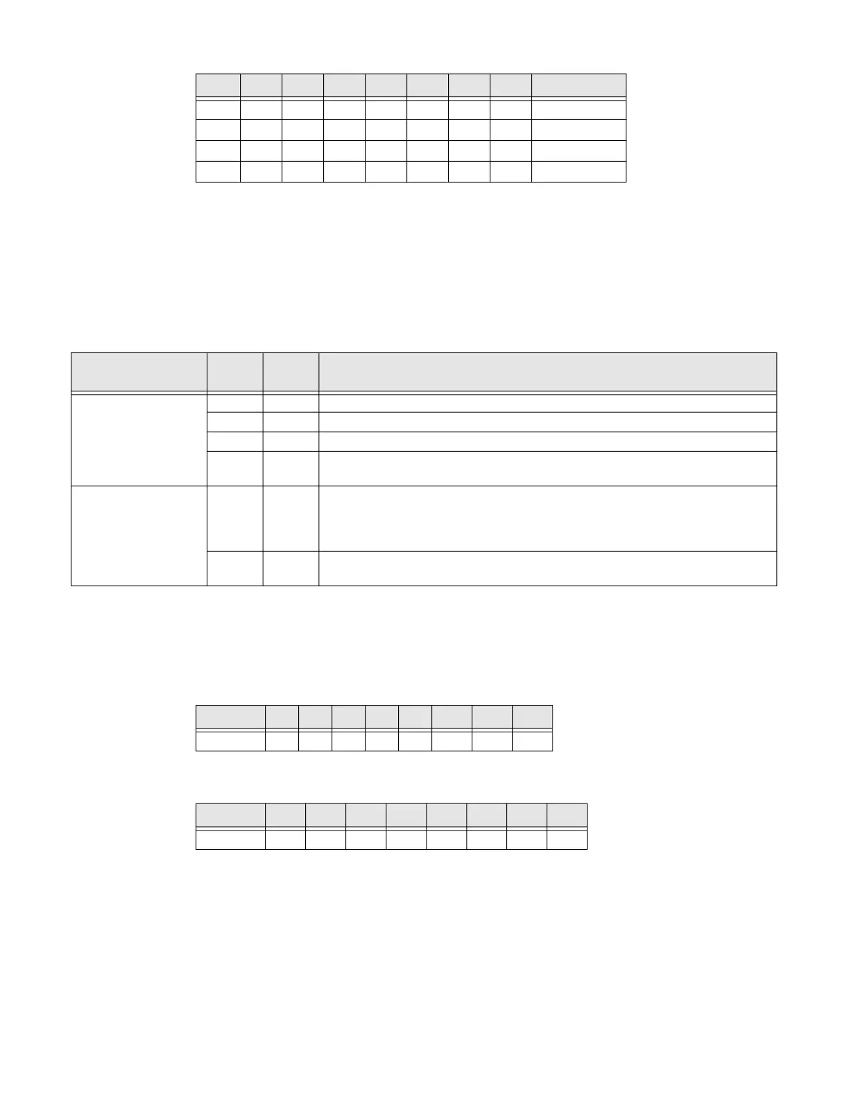
The following table lists the LEDs D1 through D4.
OFF ON 9,600 BPS
ON OFF 19,200 BPS
ON ON 38,400 BPS*
OFF
Not Used*
S8 S7 S6 S5 S4 S3 S2 S1 Selection
Mode
LED
D1
LED
D2
Description
Power-up
sequence
ON OFF Start power-up, hardware setup.
OFF ON Testing RAM.
ON ON Testing ROM and completing initialization.
FLAS
H
ON LED D1 flashes four times after power-up is completed.
Normal Operation
FLAS
H
This is the processor heartbeat LED. It flashes once every second. A short ON
time (~20% duty cycle) indicates the board is offline or has lost serial
communication with the Controller board. A long ON time (~80% duty cycle)
indicates the board is online and communicating with the Controller board.
FLAS
H
Flash when there is activity on its Serial Port.
RELAY # 0 1 2 3 4 5 6 7
LED
D5 D6 D7 D8 D9 D10 D11 D12
RELAY # 8 9 10 11 12 13 14 15
LED
D13 D14 D15 D16 D17 D18 D19 D20
 Loading...


