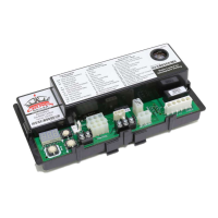
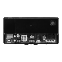
S9200U1000 UNIVERSAL HOT SURFACE IGNITION INTEGRATED FURNACE CONTROL
69-2075—01 12
to zero (0) seconds. To change it, first disconnect the
power, then set SW1 on DIP switch S1 according to
Table 8 on page 11.
HEAT FAN ON DELAY TIMING
The Heat Fan Off Delay is the period between entering
the Trial for Ignition period and the activation of the blower
motor at the heat speed (if the Trial for Ignition is
successful). The default factory setting is 30 seconds. To
change it, first disconnect the power, then set SW2 on
DIP switch S1 according to Table 8 on page 11.
HEAT FAN OFF DELAY TIMING
The Heat Fan Off Delay is the period between the loss of
supervised main burner flame after the call for heat has
ended and the deactivation of the blower motor at the low
heat speed. The timing is factory-set to 120 seconds. To
change it, first disconnect the power, then set SW3 and
SW4 on DIP switch S1 according to Table 8 on page 11.
DIP Switch S2 - Safety Timings
Table 9 and Fig. 7 describe the S1 DIP switch settings.
The default factory settings are all OFF and are shown in
bold.
Fig. 7. DIP Switch (S2) shown with factory default
settings; all OFF.
THERMOSTAT TYPE
The S9200U1000 will accept either a conventional 24
Vac, 1-Stage Heat, 1-Stage Cool thermostat or the
VisionPRO or FocusPRO EnviraCOM™ enabled
thermostats.
NOTE: When using a conventional 24 Vac thermostat,
set the Heat Anticipator to 0.1 A.
TWINNING
EnviraCOM™ communication between two S9200U1000
controls permits the controls' use in Twinning applications.
When a second S92000U1000 is sensed on the
EnviraCOM™ Bus, each S9200U1000 control proceeds
into Twinning Mode. If one of two S9200U1000 controls is
removed from a Twinning application, the remaining
control reverts back to standard operation only after
power to the control is cycled.
For twinning applications, Honeywell recommends that
DIP switch S1 be set to the same positions on each
device so that the heat/cool fan on/off delay times are
equal for both devices. Otherwise, the shorter Fan On
delay and the longer Fan Off Delay times are used for
both devices.
See Fig. 8 for typical wiring connections.
IMPORTANT
1. For Twinning applications, two S9200U1000
controls must be used.
2. Always power down appliances when wiring the
controls in Twinning applications. Failure to do
so may result in delays in the control's registra-
tion on the EnviraCOM™ Bus.
3. Fan timing changes may be detected when two
appliances are Twinned.
.
Fig. 8. Typical wiring for Twinning application.
Table 9. DIP Switch (S2) Settings - Safety Timings.
DIP Switch S2 Descriptions
Individual Switches
SW1 SW2
HSI Igniter Warm-up Time = 17/27
a
seconds
Trial For Ignition = 4 seconds
- Ignition Activation Period = 1 second
- Flame Recognition Period = 3 seconds
This is the default setting.
a
The shorter of the two periods listed (17 seconds) applies to the first
trial only, while the longer period (27 seconds) applies to the
subsequent trials during the same call for heat.
OFF OFF
HSI Igniter Warm-up Time = 17/27
a
seconds
Trial For Ignition = 6 seconds
- Ignition Activation Period = 3 seconds
- Flame Recognition Period = 3 seconds
OFF ON
HSI Igniter Warm-up Time = 30/30 seconds
Trial For Ignition = 6 seconds
- Ignition Activation Period = 3 seconds
- Flame Recognition Period = 3 seconds
ON OFF
HSI Igniter Warm-up Time = 30/30 seconds
Trial For Ignition = 8 seconds
- Ignition Activation Period = 5 seconds
- Flame Recognition Period = 3 seconds
ON ON
S2
M24910
SAFETY TIMINGS
ON
12
ON
M24917
EnviraCOM™
THERMOSTAT
CONVENTIONAL THERMOSTAT
Y
G
W
C
R
E-COM
D/1C/3
R/2W
G
Y
E-COM
D/1C/3
R/2W
G
Y
USE ONLY ONE THERMOSTAT WITHIN THE SYSTEM.
1
1
AC/C
UNIT
GND
3
2
1

 Loading...