S9200U1000 UNIVERSAL HOT SURFACE IGNITION INTEGRATED FURNACE CONTROL
19 69-2075—01
TROUBLESHOOTING
WARNING
Fire, Explosion, or Electrical Shock Hazard.
Can cause severe injury, property damage, or death.
Do not attempt to modify the physical or electrical
characteristics of this device in any way. Replace
it if troubleshooting indicates a malfunction.
IMPORTANT
1. The status codes outlined in Table 10, Table 11,
and Table 12 beginning on page 19 are a gen-
eral guide. Follow appliance manufacturer ser-
vice instructions when available.
2. Take all meter readings within the Trial for
Ignition period. After the ignition period ends,
before continuing, reset the system by turning
down the thermostat for at least five seconds but
for less than 20 seconds.
3. If any component does not function properly,
make sure it is correctly installed and wired
before replacing it.
4. Static discharge can damage the integrated
furnace control. Touch an appliance metal
surface to discharge static electricity before
touching the furnace control.
5. The S9200U1000 cannot be repaired. If it
malfunctions, replace it.
6. Only trained, experienced service technicians
should service integrated furnace control systems.
Perform the checkout steps listed in “Checkout” on
page 13 before beginning any troubleshooting
procedure. After troubleshooting, check out the
system again to be sure it is operating normally.
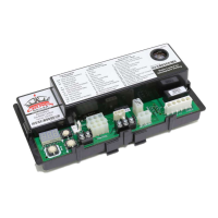
LED Indicators
The S9200U1000 has three LEDs. The three LEDs from
left to right as shown in Fig. 4 on page 9 are:
• Flame – Amber LED
The Amber LED Indicates flame status such as weak
or no flame. The Flame status codes are mapped in
Table 10.
• STATUS – Red LED
The Red LED indicates general system status, such as
the presence of a call for heat and various error codes.
The Status LED Status codes are mapped in Table 11
on page 20.
• E-COM – Green LED
This Green LED indicates EnviraCOM™ transmission
is underway. The LED is directly linked to communica-
tion on the EnviraCOM™ bus. The E-COM LED Status
codes are mapped in Table 12 on page 21.
— A typical transmitted message appears as a rapid
flashing of the green LED.
— A typical received message appears as single
blink, indicating the S9200U1000 has acknowl-
edged the message.
NOTE: The E-COM LED is active even if a conventional
thermostat is controlling the appliance.
Flash Code Descriptions
The LEDs will flash codes at various intervals. Each pulse
type indicates a specific functionality/ message type.
• Periodic Blink (Normal): 0.5 second on, 0.5
second off
• Pulse: A 0.25 second flash followed by 3.75
seconds of off time.
• Heartbeat: Constant 0.5 second bright, 0.5
second dim cycles.
• Standard LED Fault Pattern (Single X
Flash): LED flashes X times at 2HZ, then off
for 3 seconds
• Advanced LED Fault Pattern (X + Y Flash):
LED flashes X times at 2Hz, remains off for one
second, flashes Y times at 2Hz, remains off for
three seconds, and then repeats.
Table 10. Flame Status Codes (Amber LED).
Flash Code
a
a
Flash Code Descriptions:
- Pulse: A 0.25 second flash followed by 3.75 seconds of off time.
- Heartbeat: Constant 0.5 second bright 0.5 second dim cycles.
- Periodic Blink: 0.5 second on, 0.5 second off. During local history recall, this fault is flashed as a 1 + 2 pattern.
Amber LED Status Code and Error Description Check / Repair
OFF Control powered- No flame Not Applicable (normal operation)
Heartbeat Control powered- Call for heat - Flame present Not Applicable (normal operation)
Periodic Blink
b
b
During local history recall, this fault is flashed as a 1 + 2 pattern.
Call for heat - Low flame current Check: Flame rod for contamination or loose wiring; low gas
pressure.
Heartbeat Call for heat - Flame sense out of sequence - Flame still present Check/Repair: Flame at burners, if present replace gas valve.
OFF All other conditions Not Applicable

 Loading...